Thermal modeling of SMWF
Thermal modeling of SMWF
This release marks the first time users can perform detailed thermal analysis for Wound Field Synchronous Machines (SMWFs) directly within FluxMotor, enabling more accurate design, optimization, and validation of these critical components.
Advanced Cooling Design Contexts
- External Cooling: Mastering Heat Dissipation to the Environment
- Forced and Natural Convection: Users can model heat transfer to the ambience through both natural convection (passive cooling) and forced convection (e.g., fan-driven air flow), or specific cooling channels, allowing for realistic representation of various operating environments.
- Radiation to the Ambient: The model accounts for thermal radiation from the machine's external surfaces to the surrounding environment, providing a more complete picture of heat loss.
- X-Factor for LPN Calibration: To fine-tune the Lumped Parameter Network (LPN) circuit for external heat exchange, "X-factor" has been introduced. This calibration factor allows engineers to adjust the thermal resistances to better match experimental data or more detailed CFD results.
Table 1. External cooling design 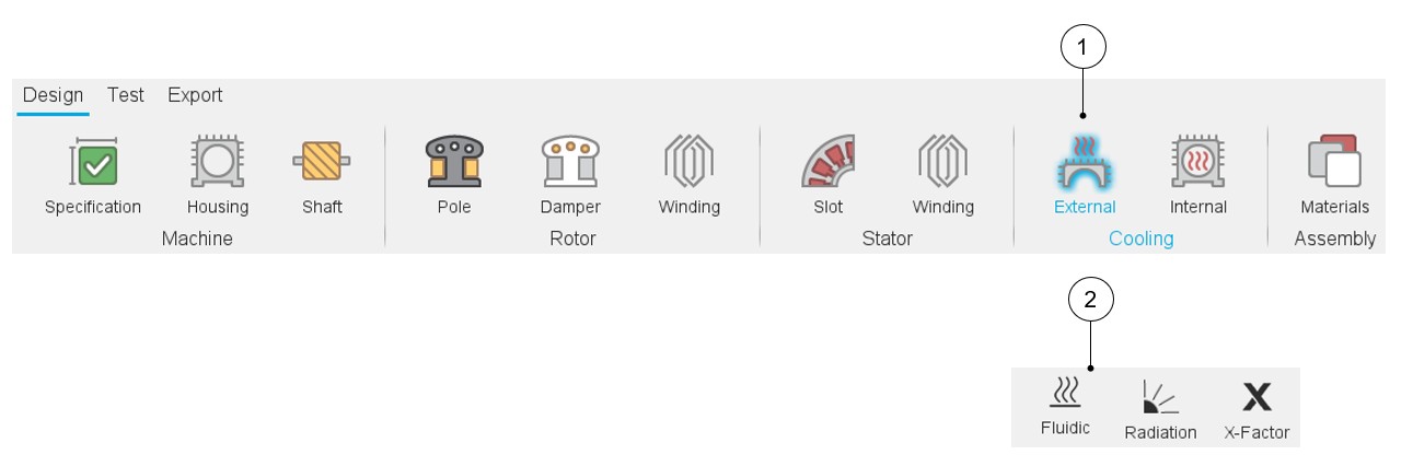
1 Main entry to the External cooling design context 2 Buttons to switch between external cooling design options - Internal Cooling: Optimizing Heat Management Within the Machine
- Forced and Natural Cooling: Like external cooling, internal cooling mechanisms, such as air circulation within the machine, can be defined for both forced and natural convection.
- Radiation Between Machine Components: Heat exchange through radiation between various internal components (e.g., rotor to stator, windings to housing) is considered, enhancing the accuracy of temperature predictions.
- Interface: Parasitic airgap thickness between machine components can be modeled in this section via Auto values or User provided values.
- Conduction Model for Slot and Field Winding: A sophisticated
conduction model has been implemented for the slot and field winding
regions. This includes:
- Auto Mode: Automatically calculates conduction paths based on material properties and geometry.
- User Mode: Provides flexibility for advanced users to manually define specific conduction parameters, allowing for highly customized thermal modeling.
- Internal X-Factor for Calibration: An additional X-factor is available for calibrating the internal LPN circuit, enabling precise adjustment of internal thermal resistances for improved model accuracy.
Table 2. Internal cooling design 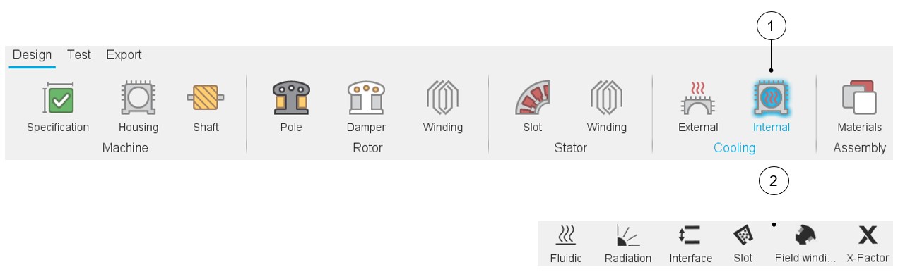
1 Main entry to the Internal cooling design context 2 Buttons to switch between internal cooling design options - Integrated Cooling Circuit Adjustments in Machine Context: The machine
context now allows for direct adjustment and definition of physical cooling
features, including:
- Housing and Fins: Model the thermal impact of external housing with or without fins for enhanced heat dissipation.
- Dedicated Cooling Circuits: Define specific cooling circuits within the machine housing.
Table 3. Machine design with new options for housing and shaft design 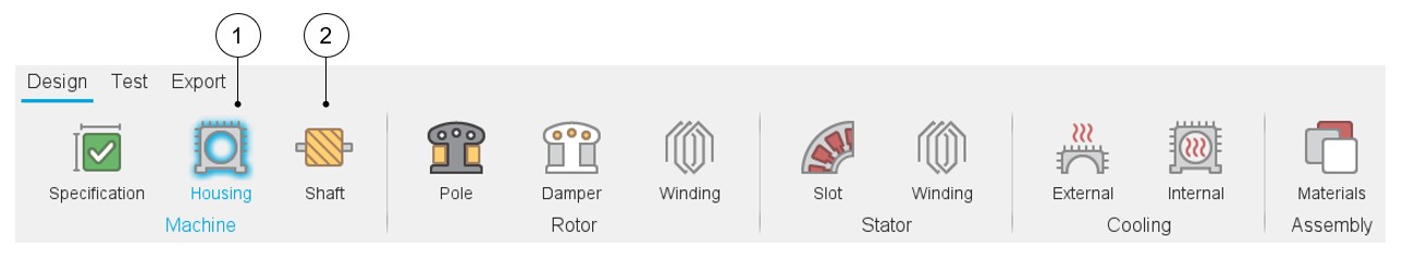
1 Main entry to the Housing design context 2 Main entry to the Shaft design context
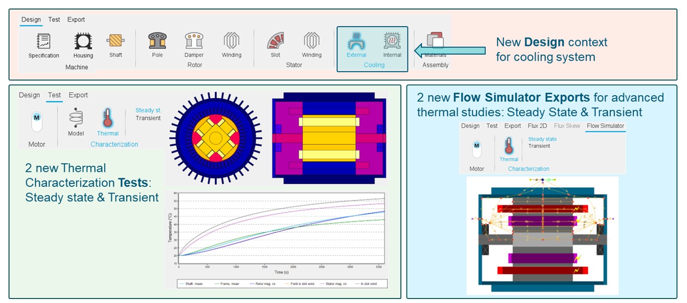
Two New Thermal Tests for SMWF
- Steady State Thermal Analysis
This test simulates the SMWF's thermal behavior at thermal equilibrium, predicting the stable temperature distribution across all components (windings, rotor yoke, stator yoke, shaft, etc.) under continuous operating conditions.
This test is essential for determining the continuous power rating, identifying critical hot spots, and ensuring that component temperatures remain within their permissible limits for long-term reliability and compliance with insulation classes.
Figure 3. The Steady state thermal test of SMWF 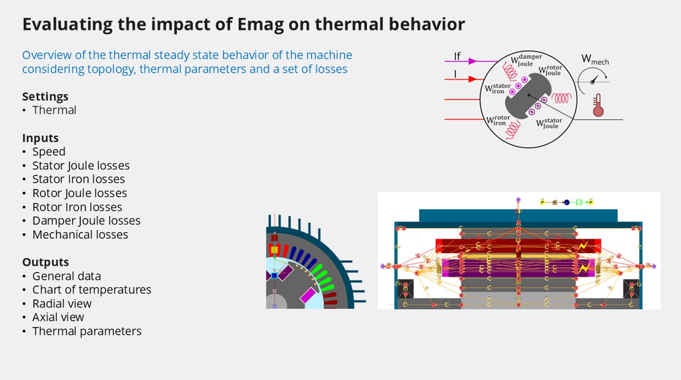
- Transient Thermal Analysis
This test simulates the dynamic thermal response of the SMWF over time, modeling how temperatures evolve during start-up, load changes, or intermittent operation.
This test is crucial for evaluating overload capabilities, understanding thermal cycling effects, predicting peak temperatures during dynamic events, and optimizing duty cycles to prevent thermal damage.
Figure 4. The Transient thermal test of SMWF 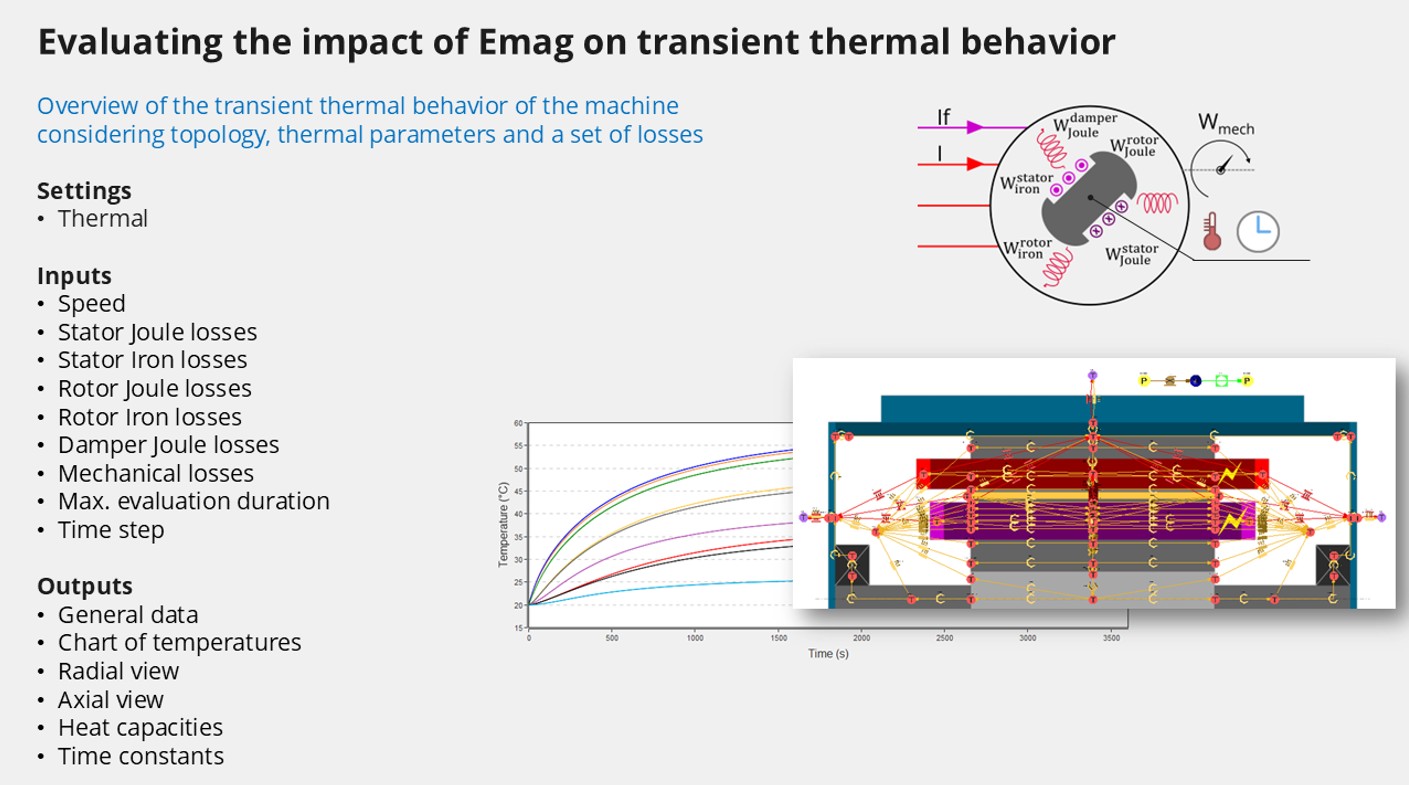
Export to Flow Simulator for Advanced Thermal Studies
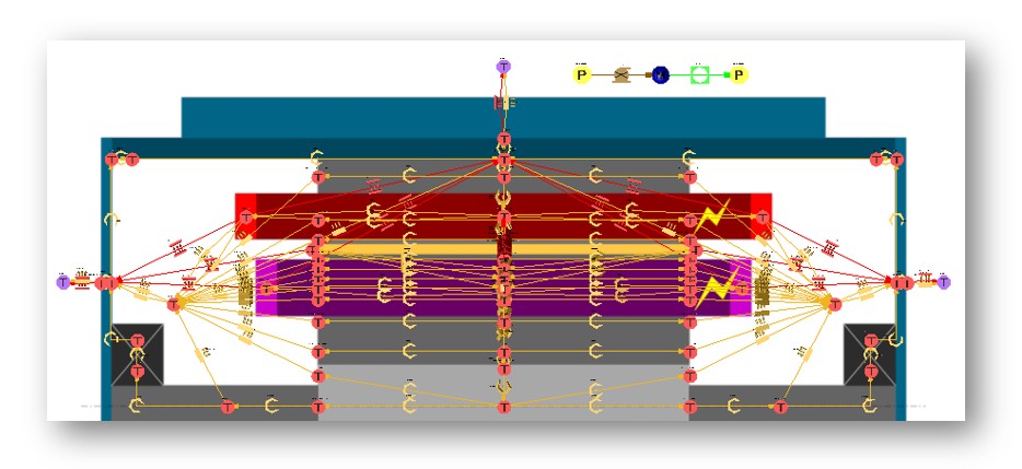
For users requiring an even deeper dive into thermal phenomena or needing to integrate the machine into a larger system-level thermal analysis, this release introduces two types of export to Altair Flow Simulator.
Users can now export their SMWF model, including the detailed thermal LPN, directly to Altair Flow Simulator. This allows for the addition of more intricate details to the thermal network that might be beyond the scope of FluxMotor's LPN.
- Steady-State Template: Configured for comprehensive steady-state thermal simulations in Flow Simulator.
- Transient Template: Set up for detailed transient thermal analysis, enabling the study of dynamic thermal behavior.
This seamless integration empowers engineers to perform highly detailed thermal validation, incorporate complex fluid dynamics, and conduct system-level thermal analysis, ensuring robust thermal performance under the most demanding conditions.