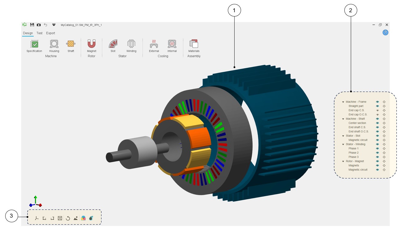
Machine 3D view
A 3D view is now displayed in the three main environments of Motor Factory: Design, Test and Export areas.
This new feature is available for every machine type.
 |
|
|---|---|
| 1 | Displaying of the machine in 3D view. |
| 2 | Tools for visualizing or not machine regions. |
| 3 | Buttons to manage the 3D view displaying. |
 |
|
|---|---|
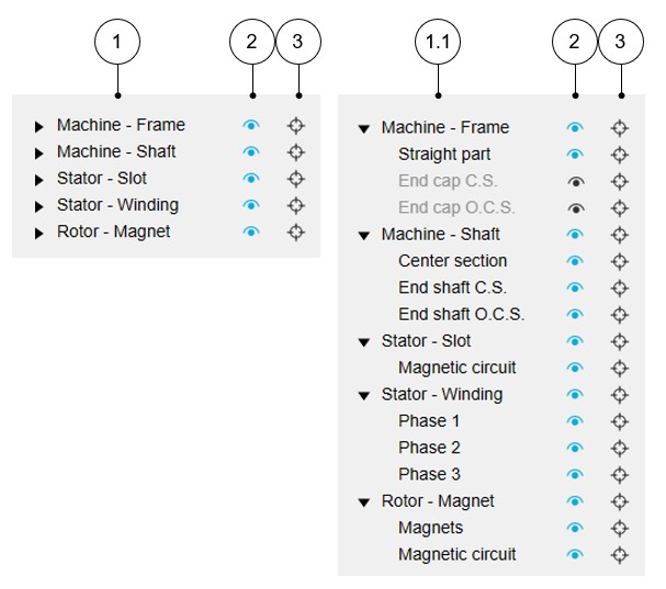
| 1 | List of the main regions of the machine. |
| 1.1 | List of the main regions and the associated sub-regions of the machine. |
| 2 | The selector (eye) allows the considered machine region to be
displayed (blue color) or not (black color). Note: When the selected “eye” is in front of a
main region label, all the associated sub-regions are
displayed. |
| 3 | The selector (target) allows us to isolate the considered machine
regions. Note: You can reset the 3D view to
reinitialize the 3D view display and make all the regions
reappear. Note: When the selected
“target” is in front of a main region label, all the associated
sub-regions are isolated. |
 |
|
|---|---|
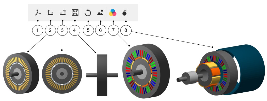
| 1 | Displaying of the machine in 3D view = default 3D view. |
| 2 | 2D view - Projection in the xOy plane. |
| 3 | 2D view - Projection in the yOz plane. |
| 4 | Reset zoom. |
| 5 | Reset the 3D view display to come back to the default 3D view. |
| 6 |
Export picture to *.png file. Note: Clicking on this button opens a dialog
box to give a name to the exported non-vector (png) picture and
a folder where to store it.
|
| 7 |
Button to display or not the FluxMotor model colors (active regions) meaning the conventional colors used in FluxMotor to represent the winding phases. This allows us to well distinguish the phase order for instance. The conventional magnet colors allow for a good distinction between the north and south polarities. Without this selection, the colors displayed represent a more realistic appearance of the different regions of the machine. |
| 8 | Button to display or not an exploded view of the machine. |