Inputs
Standard inputs
-
Field current
The current supplied to the field winding of the machine: “Field current” must be provided.
-
Line current, rms
The line current supplied to the machine: “Line current, rms” (Line current, rms value) must be provided.
-
Control angle
Considering the vector diagram shown below, the “Control angle” is the angle between the electromotive force E and the electrical current (J) (Y = (E, J)).
It is an electrical angle. The default value is 45 degrees. It must be set in a range of -90 to 90 degrees.
This range of values covers all the possible working point in motor convention.
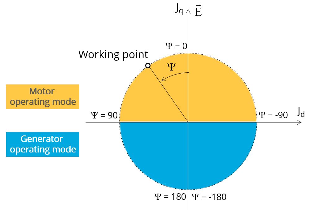
Definition of the control angle Ψ - Motor convention -
Speed
The imposed “Speed” (Speed) of the machine must be set.
-
Represented coil conductors.
In transient application, it is possible to export a project into Flux® environment, where the elementary wires will be modeled with solid conductors. The geometry, the meshing and the corresponding electric circuit will be defined to well represent these.
Three choices are possible:- • “No”: The coils will be represented with face regions. The elementary wires won’t be represented in the Finite Element model (Flux®).
- “One phase”: The elementary wires will be represented for only one phase. This will allow to compute AC losses for conductors into the first phase. This choice allows to get a good ratio between the quality of results and computation time.
- “All phases”: The elementary wires will be represented into all the phases.
Advanced inputs
The list of advanced inputs dedicated to this export are listed below.
-
Number of computations per electrical period
The default value is equal to 50. The minimum allowed value is 13.
-
Number of computed electrical periods
The default value is equal to 2. The minimum allowed value is 1 and the maximum value is equal to 10.
-
Rotor initial position
By default, the “Rotor initial position” is set to “Auto”.
-
Mesh order
The default level is second order mesh.
-
Airgap mesh coefficient
Airgap mesh coefficient is set to 1.5 by default.