Work. Pt. - Sq. wave - Motor -Forced I
1. Positioning and objective
The aim of the test “ Working point – Square wave – Motor – Forced I” is to characterize the behavior of the machine when operating with a forced current defining a square wave drive.
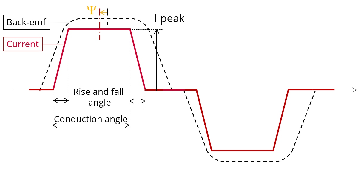
A parameterized trapezoidal shape current defines the line current.
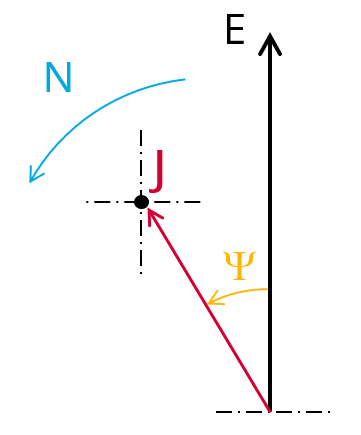
The control angle between the back-emf and the phase current, the value of current and the imposed speed induce the resulting working point. Then, the main corresponding performance are computed and displayed.
 |
 |
| Working point – Square wave – Motor – Forced I - Illustration | |
All the results are computed from a Finite Element Analysis (Flux) - Transient application. The results of this test give an overview of the electromagnetic behavior of the considered motor.
The general data of the machine, like machine constants, power balance and magnet behavior are computed and displayed.
The magnetic flux density is also computed in every region of the machine magnetic circuit to evaluate the design.
The following table helps to classify the test “Working point – Square wave – Motor – Forced I”.
| Family | Working point |
| Package | Square wave |
| Convention | Motor |
| Test | Forced I |
| Positioning of the test “Working point – Square wave – Motor – Forced I” | |
2. User inputs
The main user input parameters are the supplied line current, the speed, the control angle, the conduction angle and the rise and fall angle. In addition, temperatures of winding and magnets must be set.
3. Main outputs
Test results are illustrated with data, graphs and tables
3.1 Tables of results
-
Machine performance – working point
- General data
- Machine constants
- Power balance
- Iron losses
- Flux in airgap
- Flux density in iron
- Magnet behavior including evaluation of demagnetization rate
-
Ripple mechanical torque
- Working point
3.2 Curves
- Normalized back-emf, phase currents and mechanical torque versus time – Working point
- Phase voltage versus time – Open circuit
- Mechanical torque versus time – Working point
- Phase voltage versus time – Working point
- Line-line voltage versus time – Working point
- Phase current versus time – Working point
- Line current versus time – Working point
- Power versus time – Working point
- Losses versus time – Working point