Work. Pt. - Sine wave - Motor - T N
1. Positioning and objective
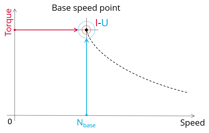
The aim of the test “ Working point – Sine wave – Motor – T, N” is to characterize the behavior of the machine when operating at the working point which is targeted by the user. It corresponds to the base point at a targeted useful torque and speed.
The working point torque-speed is defined by considering the targeted input values T, N (useful torque, speed).
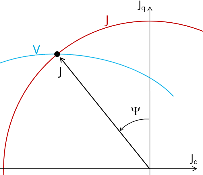
This test allows defining the required line-line voltage and line current to reach the targeted useful torque and speed for the considered command mode (MTPV, MTPA or maximum efficiency).
 |
 |
| Working point – Sine wave – Motor – T,N - Illustration | |
The results of this test give an overview of the electromagnetic analysis of the motor considering the machine topology.
The general data of the machine, like machine constants, power balance and magnet behavior are computed and displayed.
The magnetic flux density is also computed in every region of the machine magnetic circuit to evaluate the design.
The following table helps to classify the test “Working point – Sine wave – Motor – T, N”.
| Family | Working point |
| Package | Sine wave |
| Convention | Motor |
| Test | T,N |
| Positioning of the test “Working point – Sine wave – Motor – T,N” | |
2. User inputs
The main user input parameters are the mechanical torque and the targeted speed. In addition, temperatures of winding and magnets must be set.
3. Main outputs
Test results are illustrated with data, graphs and tables
3.1 Tables of results
-
Machine performance – Base speed point
- General data
- Machine constants
- Power balance
- Flux in airgap
- Flux density in iron
- Magnet behavior including evaluation of demagnetization rate
- Maximum speed estimation
-
Power electronics
- Inverter
- Working point
-
Ripple mechanical torque
- Working point
3.2 Curves
- Ripple mechanical torque versus rotor angular position
- Mechanical torque versus current and control angle
- Flux density in airgap versus rotor angular position