Saliency
1. Example
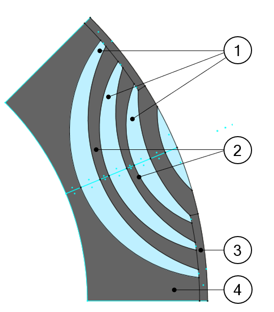
Here is an example of regions in inner saliency.
 |
|
| Regions for inner bar | |
| 1 | Flux barrier |
| 2 | Web |
| 3 | bridge |
| 4 | Yoke |
2. List of possible elementary regions for an inner saliency.
- Yoke, web, bridge, pole core, pole shoe, interpole
- Flux barrier, hub, edge
- Mechanical device to represent rivet for example
- Ferromagnetic wedge
- Hole or Slit
- Cooling hole
3. Rotor D-Axis location
The rotor d-axis location is characterized by the saliency topology.
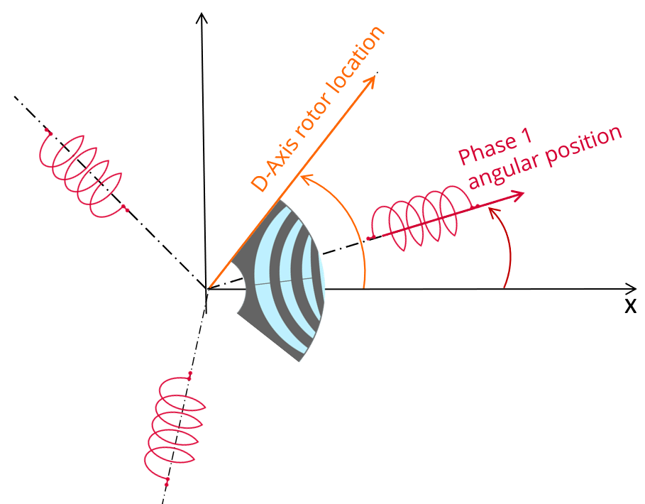
Here is below representation of the rotor and stator phase relative position
The relative angular position between the axis of the stator phase 1 (reference phase) and the rotor D-axis position must be controlled to perform the tests.
The winding axis of the reference phase is defined from the phase shift of the first electrical harmonic of the magneto motive force (M.M.F.).
This allows defining the working point of the machine.
 |
| Definition of rotor initial position – Rules for direction |
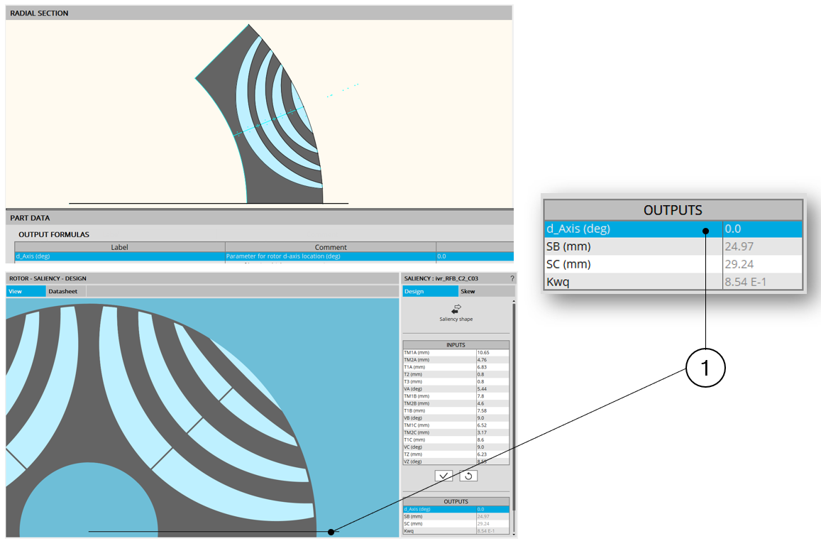 |
| Example of the rotor d-axis location: d-Axis = 0 degree |
The rotor d-axis location is an output parameter (read only data) of saliency parts. It completes the description of the topology and it is automatically used to define the relative position between the axis of the stator phase 1 (reference phase) and the rotor D-axis position for performing the tests when needed.
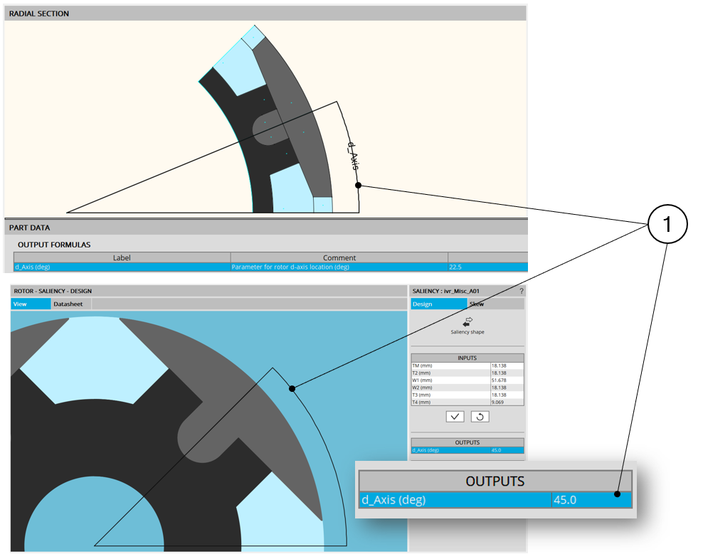 |
| Example of the rotor d-axis location: d-Axis = 45 degrees (if the rotor yoke, in black, is built with ferromagnetic material) |