Geometry building
The basic elements needed to build a part are the points, the lines, the faces and the regions.
1. Points
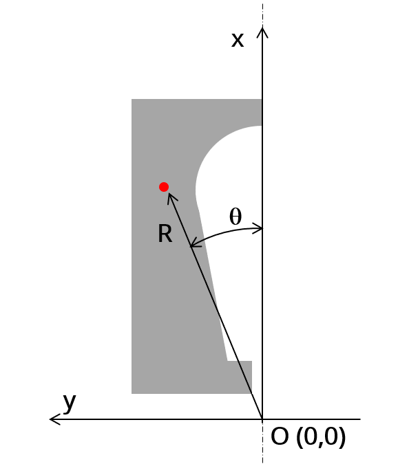
This section contains the coordinates of all points needed to build the part. These coordinates are written by considering Cartesian coordinate system and Polar coordinate system.
Below are the examples of coordinate systems for the description of slots (Symmetric or non-symmetric). The same principle is also used for magnet.
 |
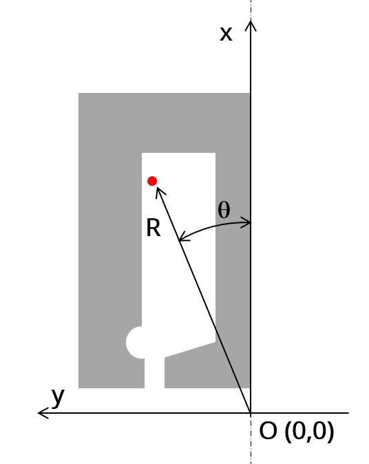 |
| Symmetric part | Non-symmetric part |
The visibility property of points can be made as “Visible”, “Invisible” or “Not exist”.
- Visible, to be used by visible and invisible lines
- Invisible, to be used by invisible lines
- No exist, for arc centersSuperimposed points are forbidden.
- All the visible points must belong to a sector.
2. Lines
This section contains the description of all the lines used in the part model.
Lines only depend on points and sector points
Two types of lines exist:
- Segment (straight lines defined with only two extremity points)
- Arc (defined in counter clock wise direction, with starting, ending and center points)The visibility property of lines can be “Visible”, “Invisible” and “No exist”.
- "Visible" to separate two faces having different properties (faces with different natures, lines separating coil conductor regions in 4 zones for adjacent and superimposed winding for example or for lines separating the airgap from the stator or the rotor etc.).
- "Invisible" when lines have not to be considered in the "part" model. An invisible line won’t be represented in the finite element model of the part.
- “No exist” when the corresponding line will be used as a support to illustrate the polarization of magnets for example. A “No exist” line will be neither used to build the geometry of the part nor to represent in the finite element model of the part.
Be aware that when the length of a visible line is very small it can lead to a model with a huge number of elements (Finite Element modeling being at the heart of our software). In this case the computation times can be very long.
3. Faces and regions
This section contains the description of all the faces and regions defined and used in the part model.
Each face is defined by a location point. The coordinates of these points are defined in a general coordinate system (Cartesian or polar) as it is described above for points.
The point must be within the corresponding face for all the values of user input parameters.
Each face has a label and a nature. The nature of faces defines the corresponding regions.
The physical properties of regions are linked to the materials that can be used to build them.
The table, below gives the physical properties of slots and magnets.
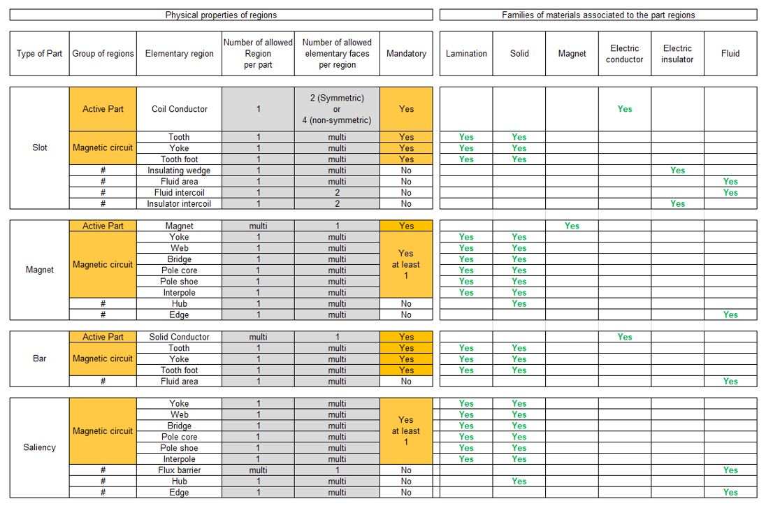 |
| Physical properties of regions and associated materials - Part 1/2 |
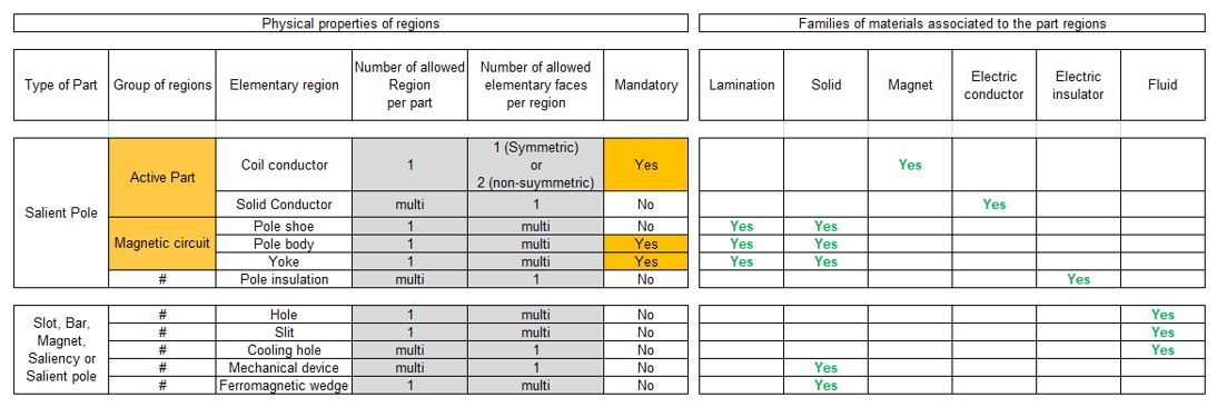 |
| Physical properties of regions and associated materials - Part 2/2 |
4. Interface gaps
"Interface gaps" regions allow describing thin regions between faces inside the topology of parts.
It can be needed for example, to represent the glue layer or a very thin airgap between two ferromagnetic regions.
This specific region is associated to a line which is visible. The thickness of the gap must be defined.
Note: The physical property of interface gap is always air.
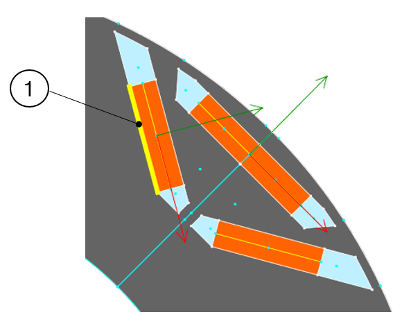 |
| An “Interface gaps” is always associated to an existing visible line (1) |
5. Parametric data
The part topology can be parameterized. Dedicated sections are provided to allow user to manage this according to the need. One section to do this is called “Internal formulas”. It allows describing all the needed formulas or expressions to define the part topology from user input parameters.
Two other sections, “Scale factors” and “Adjustment formulas” can be used when the considered part has the capability to adapt itself automatically to the sector in which it will be imported.
Let us take for example a part (Slot) defined in a sector where the structural data is as follows:
- Outer diameter =100
- Inner diameter = 50
- Number of slots = 12
What will happen if this part is imported in a machine where then stator structural data is as follows:
- Outer diameter =1000
- Inner diameter = 750
- Number of slots = 90
The aim of these two sections is to define transformation formula which allows an automatic adaptation of the part when it is imported in a new sector with differences between original and final structural data.
A dedicated tutorial is provided to explain the principles for applying these rules.
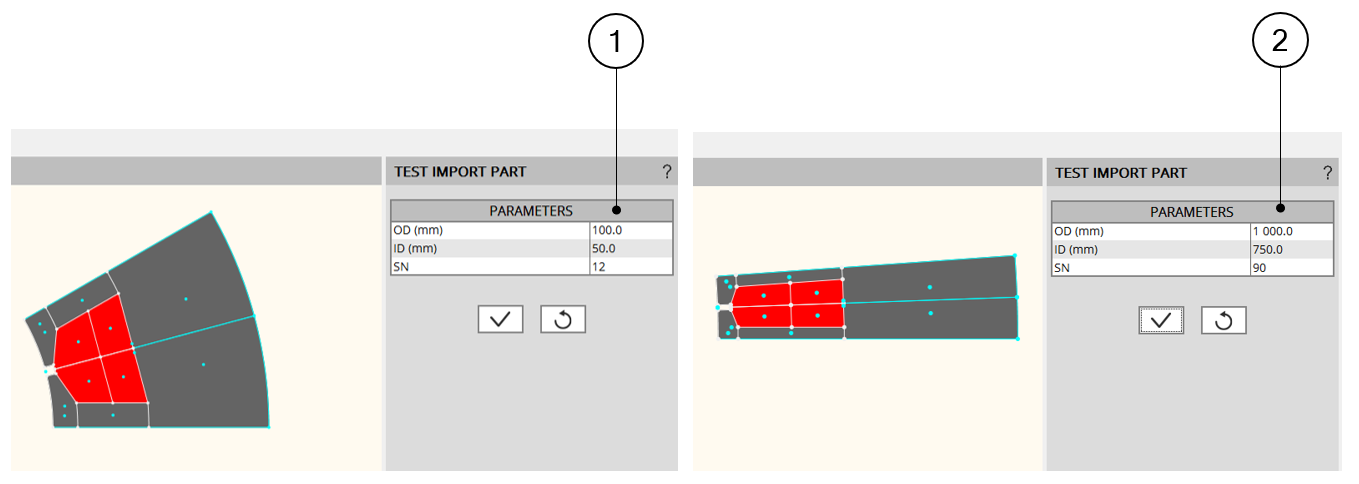 |
| Automatic adaptation of the part with the sector structural dataBy using “Scale factors” and “Adjustment formulas” |