Inputs
1. Standard inputs
-
Line current, rms
The line current supplied to the machine: “Line current, rms” ( Line current, rms value ) must be provided.
-
Control angle
Considering the vector diagram shown below, the “ Control angle ” is the angle between the electromotive force E and the electrical current (J) (Y = (E, J)).
It is an electrical angle. The default value is 45 degrees. It must be set in a range of -90 to 90 degrees.
This range of values covers all the possible working point in motor convention.
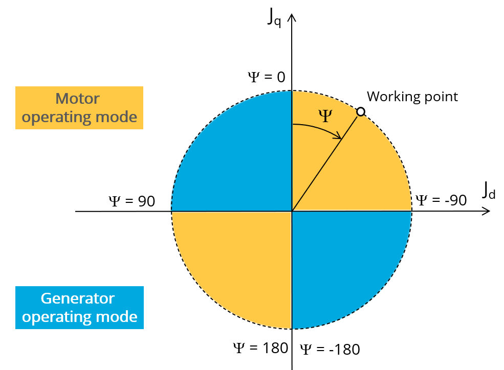
Definition of the control angle Ψ - Motor convention -
Speed
The imposed “ Speed ” ( Speed ) of the machine must be set.
-
Represented coil conductors
In transient application, it is possible to export a project into Flux environment, where the elementary wires will be modeled with solid conductors. The geometry, the meshing and the corresponding electric circuit will be defined to well represent these.
Three choices are possible:
- “No”: The coils will be represented with face regions. The elementary wires won’t be represented in the Finite Element model (Flux).
- “One phase”: The elementary wires will be represented for only one phase. This will allow to compute AC losses for conductors into the first phase. This choice allows to get a good ratio between the quality of results and computation time.
- “All phases”: The elementary wires will be represented into all the phases
2. Advanced inputs
The list of advanced inputs dedicated to this export are listed below.
For more details, please refer to the "List of generic advanced inputs".
-
Number of computations per electrical period
The default value is equal to 50. The minimum allowed value is 13.
-
Number of computed electrical periods
The default value is equal to 2. The minimum allowed value is 1 and the maximum value is equal to 10.
-
Mesh order
The default level is second order mesh.
-
Airgap mesh coefficient
Airgap mesh coefficient is set to 1.5 by default.
3. List of generic advanced inputs
-
Number of computations per electrical period
The number of computations per electrical period “ No. comp. / elec. period ” (Number of computations per electrical period) influences the accuracy of results and the computation time.
The default value is 50. The minimum allowed value is 13. This default value provides a good compromise between the accuracy of results and computation time.
-
Number of computed electrical periods
The default value is 2. The minimum allowed value is 1 and the maximum value is equal to 10.
-
Mesh order
To get results, Finite Element Modelling computations are performed.
The geometry of the machine is meshed.
Two levels of meshing can be considered: First order and second order.
The default level is second order mesh.
Airgap mesh coefficient
The advanced user input “ Airgap mesh coefficient ” is a coefficient which adjusts the size of mesh elements inside the airgap. When one decreases the value of “ Airgap mesh coefficient ”, the size of the mesh elements reduces, thus increasing the mesh density inside the airgap and the accuracy of results.
The imposed Mesh Point (size of mesh elements touching points of the geometry) is described with the following parameters:MeshPoint = (airgap) x (airgap mesh coefficient)
Airgap mesh coefficient is set to 1.5 by default.
The variation range of values for this parameter is [0.05; 2].
0.05 gives a very high mesh density, and 2 gives a very coarse mesh density.
CAUTION: Be aware, a very high mesh density does not always mean a better result quality.However, this always leads to a huge number of nodes in the corresponding finite element model. So, it means the need of huge numerical memory, and respectively computation time increases considerably.
-
Rotor d-axis location
The computations are performed by considering a relative angular position between rotor and stator.
For the reluctance synchronous machines, the rotor d-axis location is defined and automatically used to perform computations.
This value is characterized by the saliency topology. This is important to keep in mind this information it.
For more details, please refer to the document: MotorFactory_2026_SMRSM_IR_3PH_Test_Introduction – section “Rotor and stator relative position”.