Power electronics mode settings
1. Overview
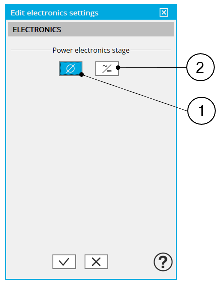
A dedicated dialog box allows the user to operate the motor with power electronic stage or without power electronic stage.
The following tests are concerned by this feature:
- Characterization / Model / Motor / Maps
- Working point / Sine wave / Motor / I, Ψ, N
- Working point / Sine wave / Motor / I, U
- Performance mapping / Sine wave / Motor / Efficiency map
- Mechanics / Sine wave / Spectrogram / T-N
 |
|
| 1 | Button to not consider power electronics stage (=default mode) |
| 2 | Button to define the user parameters of the power electronic mode |
2. Power electronics parameters
2.1 Overview
When available, the selection of the “Power electronics mode” gives access to a dedicated list of user input parameters.
The number of user parameters to define depends on the selected test. (refer to the section 3.5 - Power electronic and tests)
The whole list of power electronics parameters is illustrated below.
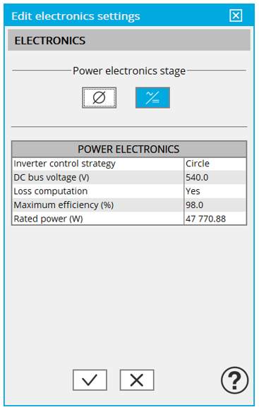 |
| Power electronics mode: whole list of input parameters |
2.2 DC bus voltage and Inverter control
The variation range of values of DC bus voltage is ]0; +inf. [
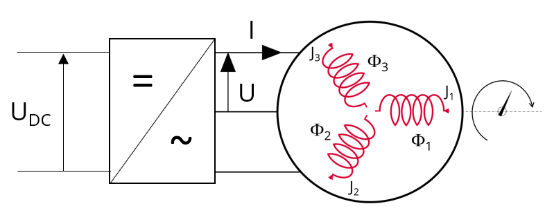 |
| Voltage and current inputs of the power electronics stage and electrical machine |
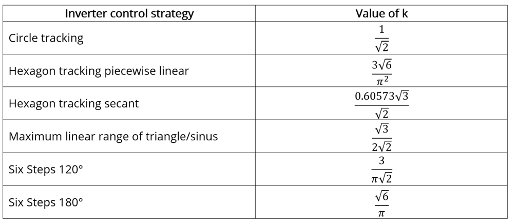
The chosen inverter control drives the ratio between the DC bus voltage and the line-line voltage seen at the machine terminal. This ratio is defined as
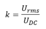
Where U DC is the DC bus voltage before inverter stage and U rms is the rms value of the first harmonic of the line-line voltage at the terminal ends of the machine.
The considered inverter control strategies and their corresponding values of k are listed in the table below.
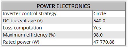
2.3 Loss computation
An internal process allows evaluating the power dissipated in the power electronics stage and its efficiency.
To get the result of this computation the user input Loss computation (Power electronics loss computation) must be set to “Yes”. The default value is “No”.
When this input is set to “Yes”, the computation of power electronics losses and efficiency is performed based on two other parameters to define: The maximum efficiency and the rated active power of the power electronic device to consider.
2.4 Max. Efficiency (Maximum power electronics efficiency)
This parameter defines the maximal efficiency that the power electronics stage can reach. This efficiency can correspond to the efficiency of an inverter or a variable speed drive.
The losses occurring in the power electronics stage are computed using this parameter and the “Rated power” settings
Max. Efficiency is set to 98% by default.
The variation range of values for this parameter is [10; 100[
2.5 Rated power – inverter or variable speed drive
This parameter defines the rated active power of the power electronic stage to consider.
It corresponds to the maximum active power that the power electronics stage (inverter or variable speed drive) can deliver without being overloaded.
The losses occurring in the power electronics stage are computed using this parameter and the parameter “Max. Efficiency”.
The rated power default value is defined from the default values of the system (machine and inverter) input voltage and current.
The variation range of values for this parameter is [0; +inf. [
- The internal process for evaluating the power electronics efficiency versus its rated power is based on analytical empirical formula.
- Only the first harmonic is considered to compute the behavior of machines. Induced losses due to the switching frequencies are not considered.
3. Advice for use
- The internal process defining the power electronics stage gives null efficiency and losses when no power entering into the power electronics stage. This is a limit of the used model. Physically, losses are not equal to zero at this point, because switching creates losses even when no power is transmitted.
- For working points above the rated power of the power electronics stage, the model efficiency is decreasing until zero. (Between 120 and 150% of the rated load, depending of the selected inputs).
- Warning, the given efficiency and losses are not qualified and cannot be guaranteed beyond 100% of the rated electrical active power.
- For a variable speed drive, when the DC bus voltage is not known, set the DC bus voltage to a value slightly lower than the maximum AC voltage provided by the grid.
- To impose the voltage directly at the machine terminals, when using the power electronics mode, set the desired peak value voltage at the machine terminals in the field “DC voltage”, and choose the command “circle” on the inverter.
4. Dedicated outputs
When power electronics is active, the line-line voltage at the machine terminals and the DC bus voltage are computed / displayed.
Moreover, when the “loss computation” is selected by the user, additional output data are computed and/or displayed.
The losses and the efficiency are computed for the machine, the power electronics stage and the system. The “system” gathers the machine and the power electronics stage.
Then, the electrical power is computed for both the machine and the system.
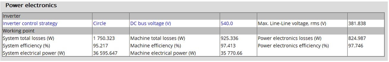 |
| Power electronics mode with loss evaluation – Example of dedicated output table |
5. Power electronic and tests
The available input parameters dedicated to the power electronics mode depend on the considered test.
Below is the table in which are defined the correspondence between the tests and the input parameters of the power electronics mode.
The whole list of input parameters is illustrated below.
 |
| Whole list of input parameters dedicated to power electronics |
| InverterCtrl. strategy | DCbus voltage | Losscomputation | |
| Characterization / Model / Motor / Maps | - | - | Available |
| Characterization / Model / Motor & Generator / Maps | - | - | - |
| Working point / Sine wave / Motor / I-Ψ-N | Available | - | Available |
| Working point / Sine wave / Motor / I-U | Available | Available | Available |
| Working point / Sine wave / Generator / I-Ψ-N | - | - | - |
| Performance mapping / Sine wave / Motor / Efficiency map | Available | Available | Available |
| Performance mapping / Sine wave / Generator / Efficiency map | - | - | - |
| Mechanics / NVH / Working Point / I-Ψ-N | - | - | - |
| Mechanics / NVH / Spectrogram / I-Ψ-N | - | - | - |
| Mechanics / NVH / Spectrogram / T-N | Available | Available | Available |
- Loss computation uses Max. efficiency and rated power user inputs
- “-“ means the parameter is not used in the considered test