Inputs
1. Standard inputs
-
Line-line voltage, rms
The line-line voltage supplied to the machine: “Line-line voltage, rms” ( Line-line voltage, rms value ) must be provided.
-
Slip or Speed mode
There are two usual parameters to define the working point. It can be defined by the slip “ Slip ” or by the rotor speed “ Speed ”.
-
Slip
If the “Definition mode” is “ Slip ”, the value of the machine’s slip must be provided, and the corresponding speed is deduced.
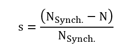
The slip “s” in the following relations) corresponds to the relative difference between the synchronous speed (N Synch. ) and rotor speed N:
-
Speed
If the “Definition mode” is “ Speed ”, the targeted rotor speed must be provided, and the resulting slip is deduced.
-
Power supply frequency
The power supply frequency corresponds to the electrical frequency of the stator magnetic field.
2. Advanced inputs
The list of advanced inputs dedicated to this export are listed below.
For more details please refer to the list of generic advanced inputs.
-
Skew number of layers
Even the design of the machine is defined with “continuous skew” that “ Skew number of layers ” is necessary for Flux® to define the finite elements model in the Flux® Skew environment.
A high number of layers gives more accurate finite elements computations.
However, it needs higher computation time. For that purpose, the value 3 is a good compromise between accuracy and speed.
Default value is 3.
-
Number of computations per electrical period
The default value is equal to 50. The minimum allowed value is 13.
-
Number of computed electrical periods
The default value is equal to 2. The minimum allowed value is 1 and the maximum value is equal to 10.
- Rotor initial position
-
Mesh order
The default level is second order mesh.
-
Airgap mesh coefficient
Airgap mesh coefficient is set to 1.5 by default.