Project Parameters: IRT General Tab
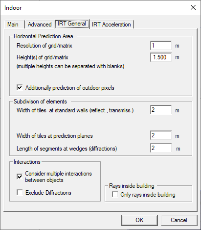
- Resolution of grid / matrix
-
This value defines the basic resolution (in meters) the prediction will be computed with. If the Adaptive Resolution Management (ARM, see below under
Acceleration
) is enabled, the resolution is changed accordingly.Appropriate values are from 0.5 meters to 5 meters, 1 meter is typical. The smaller the resolution, the higher the computation time and the higher the size of the IRT database, because the visibility relations for more pixels must be computed.
In general, it is advisable to rather keep a smaller resolution but choose a higher value for the reduced resolution. For example, it would be better to choose 1 meter with a reduced resolution factor of 3 instead of 1.5 meters with a reduced resolution factor of 2.
The advantage would be that in critical parts of the prediction area (for example, narrow corridors) the prediction is done in a smaller resolution, with the computation time and the database size hardly increasing.
This setting does not influence the resolution the building geometry is processed with. The building geometry is always processed at highest precision.
- Height(s) of grid/matrix
- This parameter defines the prediction height or heights as absolute z-coordinate
values. A pre-processing for multiple heights is possible. The individual heights
must be separated by commas then, for example,
1.2, 2.0, 4.5
. The usage of multiple heights in IRT pre-processing leads to higher pre-processing times and larger IDI databases. - Additionally prediction of outdoor pixels
- If this check box is selected, also the pixels of the database that are outside the building will be pre-processed (a prediction in the outdoor vicinity of the building is also possible). If the check box is not selected, the pre-processing is limited to the inner of the building. This option is only available if a shape has been determined.
- Width of tiles at standard walls
-
This option defines the maximum size of the tiles the walls are divided. If a wall is smaller than the given value, it is not divided but handled as the whole wall. The smaller the value is chosen, the longer the pre-processing and computation time and the larger database size get, because the visibility relations for more tiles must be computed. On the other hand, the prediction accuracy is higher.
Suggested values are 0.5 – 10 meters, typical is 2 meters.
- Width of tiles at prediction surfaces
-
The resolution of prediction surfaces can differ from the resolution of standard walls. Each wall can be enabled for a prediction on its surface separately. The user has the possibility to assign a different resolution to walls with enabled surface predictions than to the other walls.
This option defines the maximum size of the tiles prediction surfaces are divided. If a prediction surface object is smaller than the given value, it is not divided but handled as the whole object. The smaller the value is chosen, the longer the pre-processing and computation time and the larger database size get, because the visibility relations for more tiles must be computed. On the other hand, the prediction accuracy is higher.
Suggested values are 0.5 – 10 meters, typical is 2 meters.
- Length of segments at wedges
- This option defines the maximum size of the horizontal and vertical segments the wedges are divided into. If a wedge is smaller than the value given, it is not divided but handled as the whole wedge. The smaller the value is chosen, the longer the pre-processing and computation time and the larger database size get, because the visibility relations for more segments must be computed. On the other hand, the prediction accuracy is higher. Typical values are 0.5 – 10 meters, the default is 2 meters.
- Only rays inside the building
- Enabling this option causes rays to end at the outer wall of the building. This
option should not be enabled if the building has the shape of an
L
or something similar. If the building has the shape of a rectangle this option can be enabled to save computation time. This option is only available if a shape has been determined for the building. - Interactions
-
- Consider multiple interactions between objects
Enabling this option causes multiple rays to be considered but the simulation time increases.
If this option is disabled, ProMan computes only the direct ray plus the single reflection and single diffraction.Tip: It is recommended to select the Consider multiple interactions between objects check box.- Exclude Diffractions
- This option excludes the computation of diffractions within the whole database.