Creating a Modelica Custom Component
Tutorial Level: Advanced Learn the process of customizing a MoCustomComponent block to replace an existing Modelica Standard Library block in a model.
Attention: Available only with Twin Activate commercial edition.
The Modelica Custom Component block
is available for defining an implicit component with Modelica language. The block is
fully customizable including its ports, parameters and simulation function. The block
lets you leverage existing Modelica code to create a new component or modify an existing
Modelica block.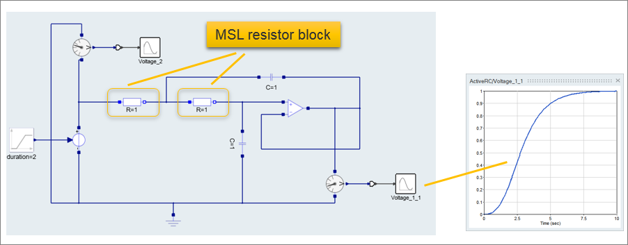
Files for This Tutorial
Active RC.scm, Active RC with custom components.scm
Defining the Modelica Custom Component
Define the ports, parameters and simulation function for a MoCustomComponent block.
-
From , select ActiveRC.scm.
The model opens in a new window.
-
From , drag and drop one MoCustomComponent block
outside of the main diagram, and double-click the block.
The block dialog appears with tabs to define the ports, parameters and simulation function for the block.
-
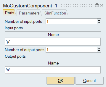
On the block dialog, select the tab, Ports, and enter
the information to define one input and one output port as you see in the
following figure:
 Important: Reviewing the Modelica MO code will help you understand what ports are required for the component.
 -
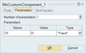
On the block dialog, select the Parameters tab. For
Number of parameters, enter 1. For Name, enter
'R', and for Value, enter
R.
-
On the block dialog, select the tab, SimFunction.
Note: Writing the simulation function requires some knowledge of the Modelica language and how it inherits (extends).
-
On the SimFunction tab:
- For Function name, enter Resistor.
- Next to the field for the Function code, click
 . In the text editor that opens, copy and paste the following Modelica
code:
. In the text editor that opens, copy and paste the following Modelica
code:model Resistor "Ideal linear electrical resistor" //MSL 2.2.1 extends Modelica.Electrical.Analog.Interfaces.OnePort; parameter Real R "Resistance"; equation R * i = v; end Resistor; - Click OK.
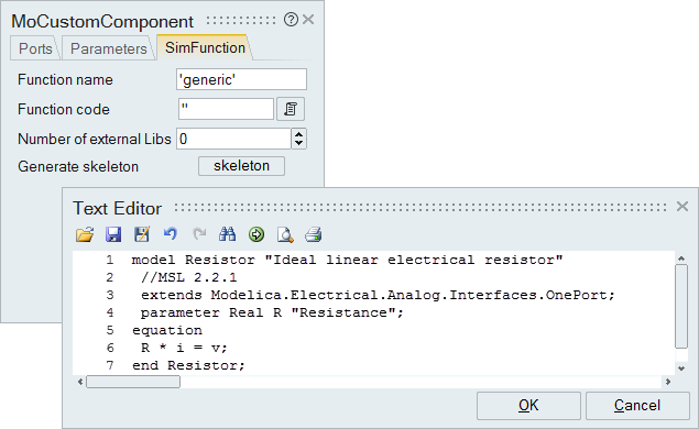 The Modelica Custom Component block is defined and ready to be connected to the model.
Implementing the Modelica Custom Component
Replace the existing R=1 resistor blocks with the Modelica Custom Component.
-
From the model, select and cut the Modelica Component,
select the left resistor, R=1, and paste the Modelica
Component block.
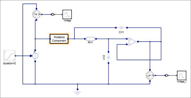
One of the two original resistor blocks is replaced with the Modelica Component. Your model should look something like this:
- Outside of the diagram, right-click and select Context.
-
In the Context menu, enter R=10, and click
OK.
Note: The value in the Context is required to complete the upcoming step of masking the super block.
- In the model, select the Modelica Component.
-
On the ribbon, select the Super Block tool:
 , or right-click and from the context menu, select Super
Block.
The Modelica Component is converted into a super block.
 -
On the ribbon, from the Mask tool group, click the
Auto Mask tool:
 .
The super block is masked.
 - Outside of the main diagram, right-click, select Context, and delete R=10.
-
In the diagram, copy the SuperBlock, select the
remaining resistor block, R=1, and paste the
SuperBlock.
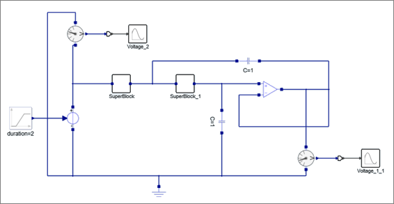
The SuperBlock replaces the second resistor block. The model now contains two super blocks: SuperBlock and SuperBlock_1.
- In the diagram, double-click SuperBlock_1.
-
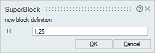
In the dialog, for R, enter 1.25.
