Co-Simulation with PSIM
Learn about co-simulation with the PSIM block.
Introduction
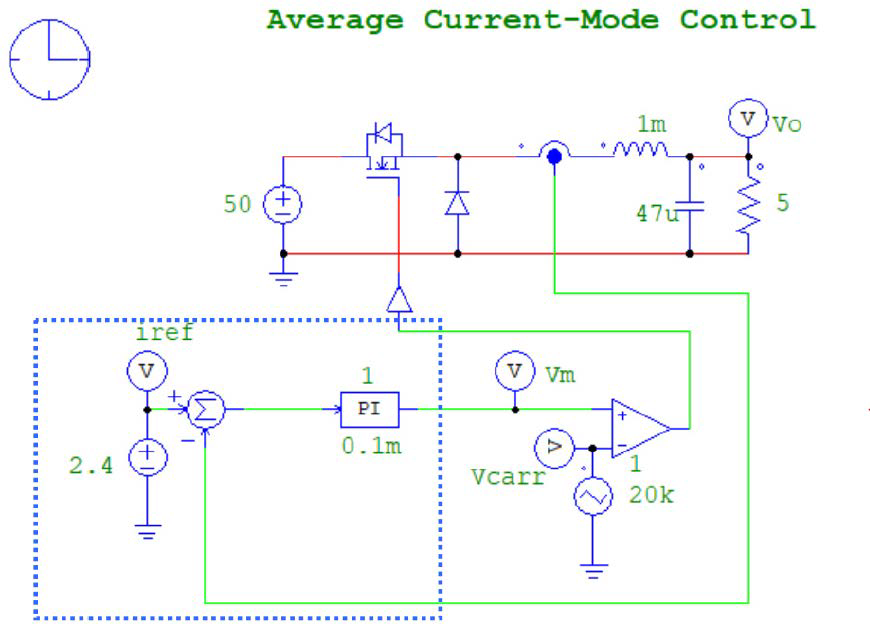
Set Up the Model in PSIM for Co-Simulation
Set up co-simulation in PSIM.
The Co-simulation with Twin Activate uses the PSIM installation path defined in your preferences.
- Launch PSIM, and open the file chop1q_ifb.psimsch. The file can be found in the sub-directory examples\SimCoupler in the PSIM directory.
- Save the file to a different name, such as chop1q_ifb_psim.psimsch, in the directory C:\test.
-
Modify the circuit by deleting the reference source, the summer, and the PI
controller.
Figure 2. The electrical circuit part to be simulated inside PSIM 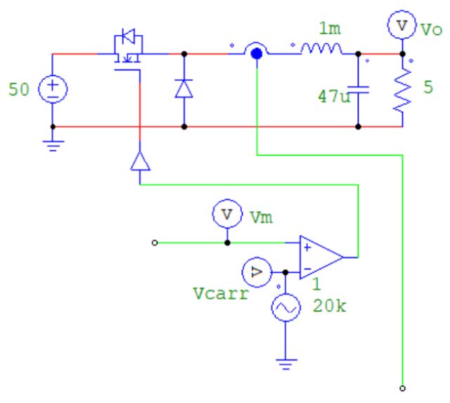
-
In order to add the communication port between Twin Activate and PSIM, the In
Link Node and Out Link Node blocks are needed. These blocks can be found in menu in PSIM. Click on these blocks
and choose names for input and output signals, as shown below.
Figure 3. In Link Node and Out Link Node in PSIM 
- Select the Out Link Node and connect it to the current sensor output, and rename it to iL.
-
Select the In Link Node and connect it to the comparator input, and rename it
to Vm.
The PSIM block in Twin Activate uses the Link nodes to establish interface between PSIM and Twin Activate. In Link Nodes receive values from Twin Activate, and Out Link Nodes send values to Twin Activate. Multiple In/Out Link Nodes can be used in a circuit to exchange values between PSIM and Twin Activate.
In this case, for example, you are going to measure and send the load voltage to Twin Activate by connecting a voltage sensor across the load resistor and placing an Out Link Node at the voltage sensor output. The Out Link Node will be renamed as Vo. After this, the circuit will look as below.
Figure 4. The electrical circuit augmented with interface In/Out link blocks inside PSIM 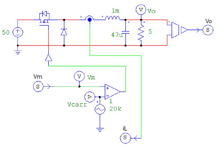
-
If there are more than one In Link Node or Out Link Node (such as in this
case), you might arrange the order of the link nodes. Go to , and a dialog window opens as shown below.
Figure 5. Changing the order of inputs and outputs. 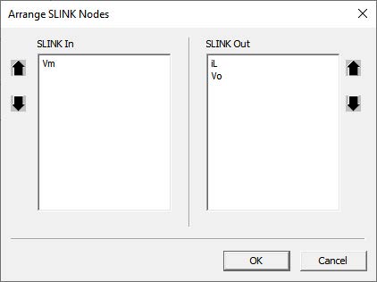
Arrange the order of the In nodes and Out nodes to be the same as how the input/output ports would appear in the PSIM block in Twin Activate. The order of the ports is from the top to the bottom. In this case, the output port corresponding to iL will be on the top, and the output port corresponding to Vo will be on the bottom. To rearrange the node sequence, highlight the name of the node, and click on the up or down arrow.
- Save the schematic file in PSIM. In this example, the file is saved to c:\test\chop1q_ifb_psim.psimsch. At this point, the setup in PSIM is complete, and setup in Twin Activate can begin.
- Launch Twin Activate and open a new model.
-
Drag and drop a PSIM block in the CoSimulation
palette, as shown in Figure 6.
Figure 6. CoSimulation palette of Twin Activate 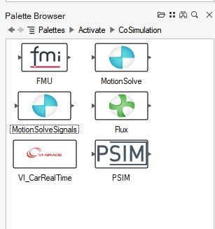
-
Click on the PSIM block and choose the
chop1q_ifb_psim.psimsch file, as shown in Figure 7. After the file is chosen, the input and output
names, as well as proposed fixed-step time and final times fields are populated
automatically. If you change the PSIM model, you
need to click the Reload button to repopulate the fields.
To directly access and modify the model, click the PSIM button.
Figure 7. The PSIM block dialog in Twin Activate 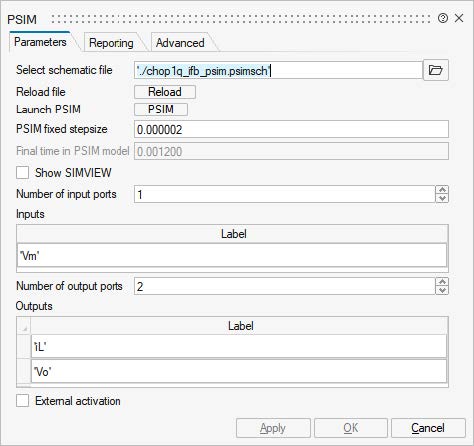
-
After the PSIM model is selected and the fields are
populated, click OK to close the dialog. Now the PSIM block should look like the figure in Figure 8 and should have the same number of input and
outputs in the PSIM environment.
Figure 8. The PSIM block in Twin Activate 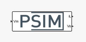
-
Build a control model corresponding to the control circuit that was deleted
from the PSIM circuit in step 3, should be built in Twin Activate, as shown in Figure 9.
Figure 9. The complete PSIM model in Twin Activate 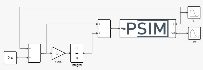
-
After the model in Twin Activate is finished, change the
Twin Activate simulation setup and choose the
appropriate simulation time and step-size. Both fixed-step and variable step
size solver can be used. Now co-simulation can be started. The simulation result
are shown in scopes.
Figure 10. The co-simulation result in Twin Activate 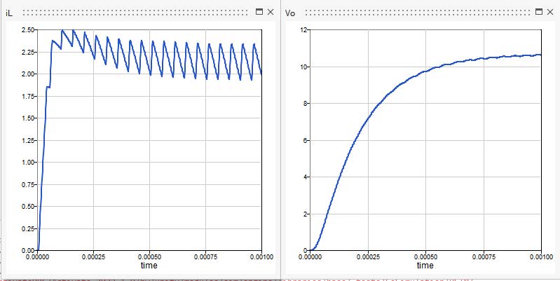
Pass Parameters from Twin Activate to PSIM
Sometimes, it is useful to use parameters in PSIM instead of numerical values.
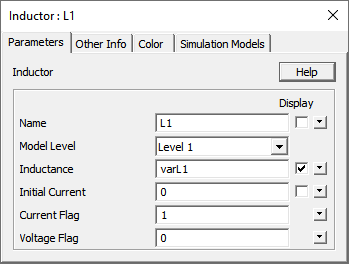
The value of these parameters can be defined and changed in Twin Activate. In order to set some parameter values in Twin Activate and pass them to PSIM, in the PSIM schematic file, change the desired value to a variable name. For example, to set the inductance of the inductor L1 in Twin Activate, you can also change it to e.g., varL1, as shown in Figure 11.
Choose the number of variables that should be passed to PSIM and provide their name and their values in the table.
In Twin Activate, double click on the PSIM block to open the dialog, and click on the Advanced tab, as shown in Figure 12. Choose the number of variables that should be passed to PSIM and provide their name in PSIM and their values in the table.
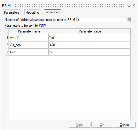
The value of parameters can be any string variable readable by PSIM. The values may also be variable in Twin Activate.
Demo models chop1q_ifb_Buck.scm and chop1q_ifb_psim.psimsch in Twin Activate Co-simulation and PSIM demonstrate this feature.
Reporting
The PSIM block can generate a logfile and all inputs and output values communicated between Twin Activate and PSIM will be logged. This is very useful in case of trouble, but it slows down the co-simulation.
The logfile can also be stdout or stderr.