Modeling with SPICE
Learn about modeling with the SPICE application, Spice custom block, and Spice library.
- SPICE Analog Application
-
SPICE, the Simulation Program with Integrated Circuit Emphasis, is a general-purpose, open source analog application for the design and simulation of electronic circuits.
Twin Activate supports the SPICE language to model and predict the behavior of all components, nodes, and connections related to electrical designs. The textual representation of the SPICE format enables you to define electronic circuitry that can be easily shared without restrictions.
- Twin Activate Spice Environment
- The combination of Twin Activate and SPICE offers an environment to simulate electronic circuitry inside of mixed-system designs. Twin Activate handles SPICE components in models by way of SPICE netlists and a high-performance electrical solver. The solver is based on the SPICE language and is dedicated to electrical circuit simulation in DC/Transient/AC modes. In addition, the solver includes an interface to Berkeley device models that handles the BSIM series MOS models.
Spice Custom Block
Define electronic components with the SpiceCustomBlock.
-
From the Palette Browser, select . Drag the block into your diagram and double-click it.
The block dialog appears with tabs for Parameters, Reporting and Advanced features.
-
From the Parameters tab, select the Editor button.
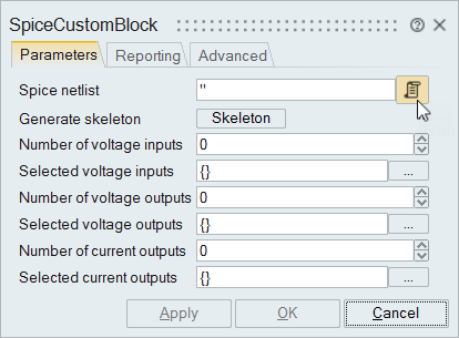
-
Enter your netlist code:
- Enter your netlist in the Editor or copy and paste it from an existing netlist file.
- If you would like to enter a netlist yourself, but are unfamiliar with
SPICE, click the
 button for the software to generate a basic
code framework for you. Click the Editor button
  to view and modify the code as required. .
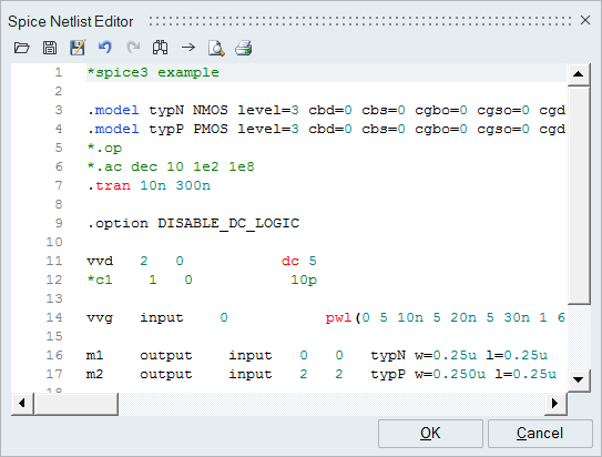
-
On the Parameters tab, enter the information for the voltage inputs/outputs and
the current outputs that are required for the block.
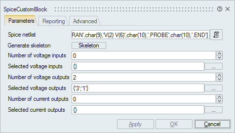
Enter the voltage output ports as a list or select them through the dialog.
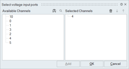
- Click OK.
Creating Electronic Components with the Spice Library
The Spice library provides the blocks for modeling electronic and microelectronic systems in Twin Activate.
The library is designed for electronic designers and system engineers and leverages the Altair Spice solver. Access to the library is available through the .
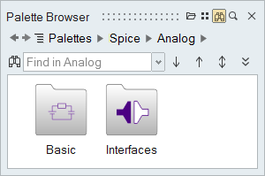
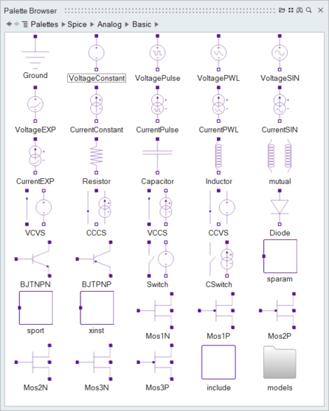
The library includes a variety of blocks including: voltage and current sources used to define the excitation and power supply for circuits; linear and semiconductor components; and interfaces to connect Spice components with other Twin Activate blocks.

Creating a Simple Diagram of an Electronic System
When modeling an electronic system in Twin Activate, two type of blocks are required from the Spice library: basic blocks, which contain the elementary SPICE components, and interface blocks, which include the connectors to combine electric circuits with other Twin Activate blocks.
When combining Twin Activate blocks with Spice blocks, the software automatically inserts the appropriate interface block as required. The following example shows an electronic system model connected to a Scope block through an interface block.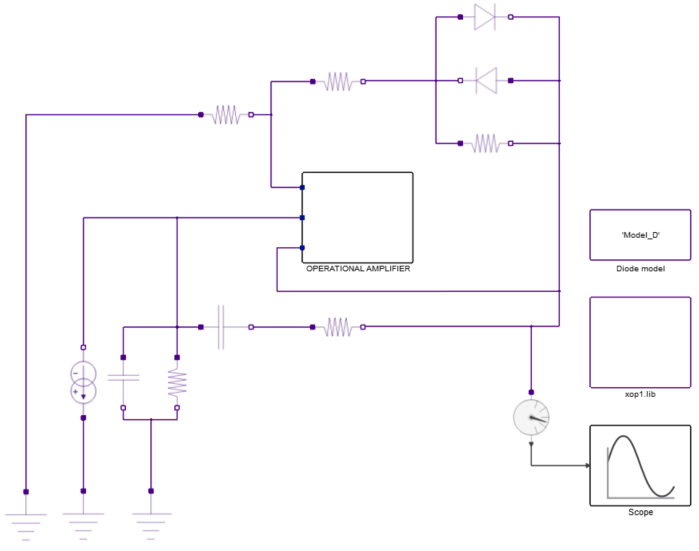
Components in the Spice library can be parametrized to set the actual physical values of the physical devices. For more details, refer to the F1 help for the individual Spice blocks.