
Symmetry
Define the symmetry boundary conditions. You can define up to two symmetry planes. The second symmetry plane must be parallel or orthogonal to the first.
- On the ribbon, click the Die Design tab.
-
Click the Part icon.
-
Click the Symmetry icon.

A blue arrow is displayed with an origin point.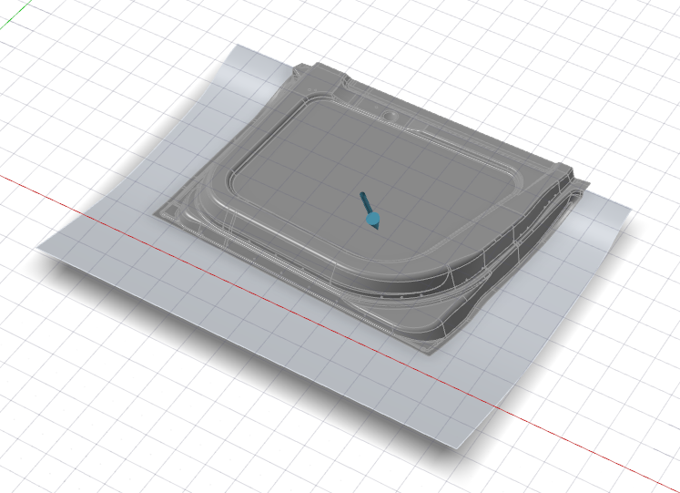
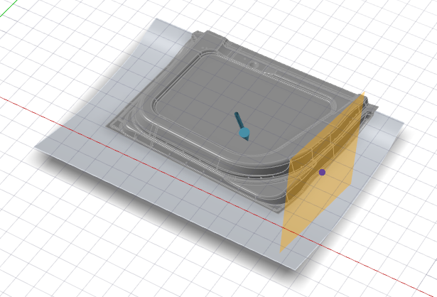
-
Hover over a part to position the symmetry plane, and then click to create the
symmetric copy.
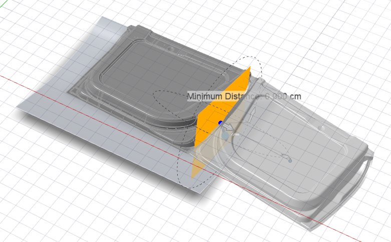
Note: To add a gap between the original part and the symmetric copy, change the Minimum Distance by dragging the yellow arrow or entering a value.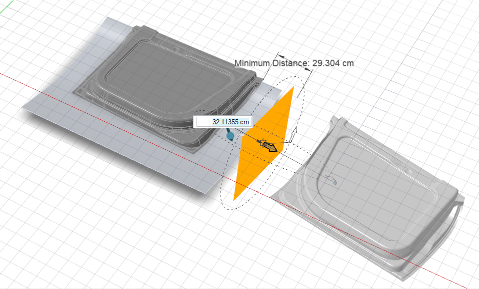
Note: To delete a symmetry plane, select it, and then press Delete. -
To add a second symmetry plane, hold down
Alt while hovering over a part to position the second
symmetry plane, and then click to create the second symmetric copy.
Note: The second symmetry plane must be parallel or orthogonal to the first.
-
Adjust the symmetry planes.
- Select the symmetry plane you want to adjust.
- Do one of the following:
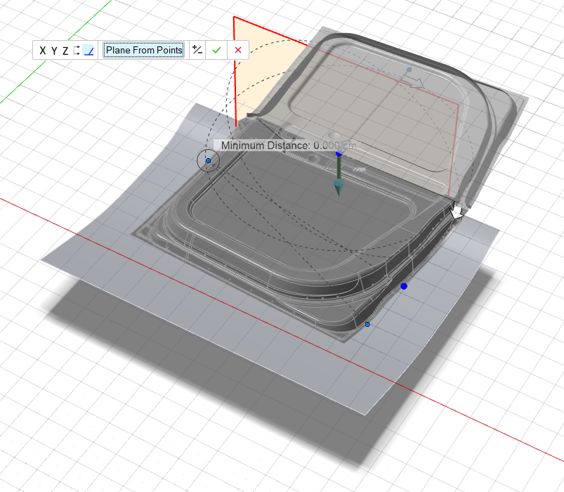
- In the microdialog, select Plane from
Points. Hover over the model to display blue
points. Click the three desired blue points to precisely define
the symmetry plane.
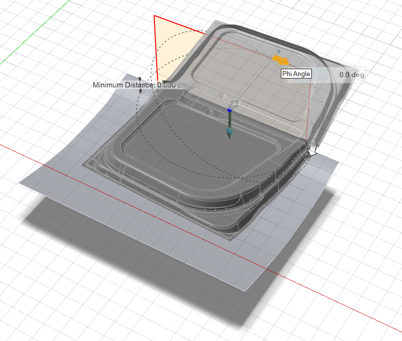
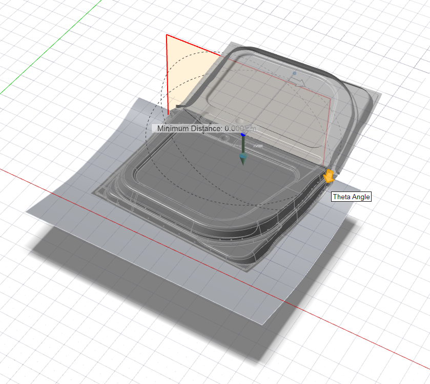
- Drag the Phi Angle and Theta
Angle arrows.
- In the microdialog, select a reference direction:
Option Description 
Global X Axis 
Global Y Axis 
Global Z Axis 
Reference Geometry: In the modeling window, click a reference curve. The symmetry plane will correspond to the plane of the reference curve, rather than be tangent to it. 
Custom : In the modeling window, drag the Phi Angle and Theta Angle arrows, or click one of the arrows and enter an angle. You can also drag the Direction Point. 
Invert Direction
- In the microdialog, select Plane from
Points. Hover over the model to display blue
points. Click the three desired blue points to precisely define
the symmetry plane.
- Right-click and mouse through the check mark to exit, or double-right-click.