
Double Attach
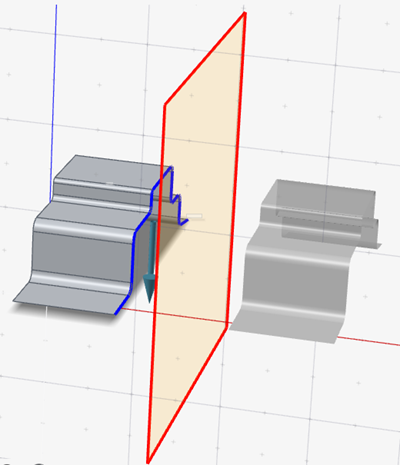
Reflect a part along the symmetry plane, then connect the edge to the symmetry plane with a new surface.
- On the ribbon, click the Die Design tab.
-
Click the Part icon.
-
Click the Double Attach icon.
 The guide bar and Control Panel appear.
 -
Select a method to create the symmetry plane.
- General: Define the symmetry plane using the default settings.
- Three points: Choose three points to create the symmetry plane.
- Draw + Two Points: Select two points to define the symmetry plane normal as orthogonal to the draw direction and the selected two points.
-
Hover over the edge of a part, then click to create the symmetry plane.
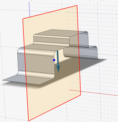
- To adjust the distance between the part and symmetry plane, use the arrows.
- In the guide bar, select Surfaces.
-
Select an edge selection method.
- Tangent Selection: When you click an edge, all tangent edges are automatically selected.
- Standard Selection: When you click an edge, all connected edges are automatically selected.
- Single Selection: When you click an edge, only one edge is selected at a time.
-
Left-click the edge where you would like to extend the surface to the symmetry
plane, then right-click to create the surface.
Note: Selectable edges are blue.
-
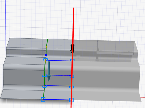
To create ribs along the surface, while holding down
Alt, click the edge.
-
To adjust the ribs, click the rib handles and modify the parameters in the
microdialog.
To Do this Adjust the rib's Tangent Magnitude to the part surface UV isoparms Enter the Tangent Magnitude. Extend the rib tangent to the part surface Turn on Extend, then enter a value for Extend Length. Table 1. Editing Options To Do this Align the symmetry plane normal to the x-axis Select  .
. Align the symmetry plane normal to the y-axis Select  .
.Align the symmetry plane normal to the z-axis Select  .
.Define the draw direction using reference geometry In the guide bar, click  , then select the reference
geometry.
, then select the reference
geometry.Edit the draw direction Select  , then drag the draw
direction manipulator.
, then drag the draw
direction manipulator.Invert the draw direction In the guide bar, click  .
.Adjust the Alpha Angle of the rib - Click the left rib handle, then drag the white arrow.
- In the microdialog, enter the Alpha Angle.
Visualize the depth of your model In the guide bar, turn on Depth Box. Visualize the negative draft of your model In the guide bar, turn on Draft Analysis. Adjust the tangent magnitude between the part surface and connecting surface at the part edge In the Control Panel, enter the Surface Tangent Magnitude. Adjust the Draft Angle In the Control Panel, enter the Draft Angle. Change the color that appears for draft angles with a degree range of 10 or higher In the Control Panel, click the dropdown arrow for  .Note: You can only view and adjust these colors if you've enabled Draft Analysis in the guide bar.
Change the color that appears for draft angles with a degree range lower than 10 In the Control Panel, click the dropdown arrow for  .
. - Right-click and mouse through the check mark to exit, or double-right-click.