
Draft Analysis
Analyze the draft and detect undercuts when designing a product that is manufactured using injection molding.
Analyze the Draft
Analyze the draft to determine whether the product will be easily removed from the mold, or if you will need to correct the draft to facilitate mold release.
The sides of the object should not be parallel to the pull direction (the direction in which the mold is pulled away from the object). Instead, they need to be angled slightly so that the mold can be pulled away from the object easily, without deformation or damage. This slight angle is called draft. The deeper the mold, the more draft needed.
- In the modeling window, select one or more objects.
- On the ribbon, click the Analysis tab.
-
Click the Draft Analysis icon.
- Optional:
Define the settings. Any modifications to the settings are automatically saved
by Inspire Studio for future use. To restore the default settings, click the
Reset button.
Option Description Reference Direction Choose from the following options: - Global Axis X (default): If the object is aligned with the world coordinate system, the mold will be pulled away from the right side of the object.
- Global Axis Y: If the object is aligned with the world coordinate system, the mold will be pulled away from the back side of the object.
- Global Axis Z: If the object is aligned with the world coordinate system, the mold will be pulled away from the top side of the object.
- Reference Geometry: If the object is aligned with another object, the mold will be pulled along the plane normal to the reference geometry (curve, edge, or face).
- Custom: Define an alternative pull direction by clicking and dragging the Direction and Origin handles in the modeling views.
- Invert Direction: Invert the pull direction. For example, if the object is aligned with the world coordinate system, select Global Axis Z and Invert Direction to indicate that the mold will be pulled away from the bottom side of the object.
Positive Draft Refers to a region where sufficient draft has been detected, in the same direction as the current pull direction.
By default, these regions appear green, but you can change the legend color using the color palette.
Draft Angle Use to define the tolerance value for sufficient draft. The default value is 1°.
Select a value that is greater than or equal to 0°; it must also be greater than or equal to the Warning Angle.
Requires Draft Refers to a region where insufficient draft has been detected.
By default, these regions appear yellow, but you can change the color using the color palette.
Warning Angle Use to define the tolerance value for insufficient draft. The default value is 0°.
It must be less than or equal to the Draft Angle.
Negative Draft Refers to a region where sufficient draft has been detected, in the direction opposite to the current pull direction.
By default, these regions appear red, but you can change the color using the color palette.
Symmetric Angle Make the draft angle and warning angle symmetric. For example, if the draft angle is 1°, the warning angle is -1°. Parting Line Display the line where the two halves of the mold meet. To facilitate mold release, features should be perpendicular to the parting line.
The parting line will still be visible after you close the Draft Analysis tool.
-
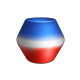
Interpret the results:
- Green indicates a region where sufficient draft has been detected, in the same direction as the current pull direction.
- Yellow indicates a region where insufficient draft has been detected; you'll need to correct the draft of this region.
- Red indicates a region where sufficient draft has been detected, in the opposite direction of the current pull direction.
- Right-click and mouse through the check mark to exit, or double-right-click.
Detect Undercuts
Detect undercuts to determine whether the product will be easily removed from the mold, or if you will need to use injection mold sliders to facilitate mold release.
An undercut is an indentation or protrusion that could prevent the object from being ejected directly from a one-piece mold. Undercuts may require sliders, which are extra parts of the mold that move separately from the two halves.
- In the modeling window, select one or more objects.
- On the ribbon, click the Analysis tab.
-
Click the Draft Analysis icon.
- For the Analysis Type, select Undercut Analysis.
- Optional:
Change the settings. Any modifications to the settings are automatically saved
by Inspire Studio for future use. To restore the default settings, click the
Reset button.
Option Description Reference Direction Choose from the following options: - Global Axis X (default): If the object is aligned with the world coordinate system, the mold will be pulled away from the right side of the object.
- Global Axis Y: If the object is aligned with the world coordinate system, the mold will be pulled away from the back side of the object.
- Global Axis Z: If the object is aligned with the world coordinate system, the mold will be pulled away from the top side of the object.
- Reference Geometry: If the object is aligned with another object, the mold will be pulled away along the plane normal to the reference geometry (curve, edge, or face).
- Custom: Define an alternative pull direction by clicking and dragging the Direction and Origin handles in the modeling views.
- Invert Direction: Invert the pull direction. For example, if the object is aligned with the world coordinate system, select Global Axis Z and Invert Direction to indicate that the mold will be pulled away from the bottom side of the object.
Occlusion Region Refers to a region where occlusion has been detected.
By default, these regions appear orange, but you can change the color using the color palette.
-
Interpret the results:
- Orange indicates a region where undercuts have been detected; you may need to use sliders to facilitate ejection in these regions.
- The number of (partially) occluded faces is displayed in the Draft Analysis panel.
- Right-click and mouse through the check mark to exit, or double-right-click.