Tutorial Level: Intermediate Create datum planes to use as clipping planes on a part/assembly to review results on a
section-cut.
Purpose
SimSolid performs meshless
structural analysis that works on full featured parts and assemblies, is
tolerant of geometric imperfections, and runs in seconds to minutes. In this
tutorial, you will do the following:
Learn to create datum planes and use them as a clipping plane for
detailed model review and cut-section results review
Model Description
The following files are needed for this tutorial:
Transmission_housing.ssp
Figure 1.
The project file has the following specifications:
Material is set to Steel for all parts
Regular and fastener connections are created
Structural analyses are created and solved for result review
Open Project
Start a new SimSolid session.
In the main window toolbar, click Open Project.
In the Open project file dialog, choose
Transmission_housing.ssp
Click OK.
Create Datum Planes
Define a plane to review analysis result for an assembly/part.
In the Project Tree, open the
Assembly workbench.
On the Assembly workbench, click Create datum
plane.
In the Origin tab, input the values for the datum plane origin (0,0,0) or
translate with the manipulator in the modeling window.
Figure 2. By default, the datum plane will be located at the COG of the imported
model.
Go to the Normal tab and input values for the orientation.
Tip: To have the datum plane 45 degrees along the XZ plane, enter
1 for X and Z.
Figure 3.
Optional: To create datum planes for specific parts, go to the Parts
tab.
Click OK to create.
Optional: Repeat the above steps to create more datum planes.
Results are generated upon creating
the datum plane, even after the analysis has been solved.
Use Datum Planes as Clipping Planes
Created datum planes can be used as a clipping plane.
On the main window toolbar, click Use datum planes as clipping plane.
All datum planes are listed in the dialog.
Select a datum plane to visualize them as a section cut on the assembly.
Figure 4.
Optional: To flip the clipping plane, click Toggle
side.
Click Cancel.
Note: By clicking OK, the dialog will close
but the clipping plane remains. To deactivate the clipping plane and bring
back the complete model, click Use datum planes as clipping plane.
Review Results
Select Teil 2, Steel from the Project Tree and press I to
isolate.
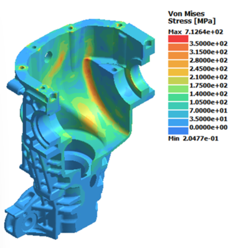
Plot von Mises from Structural 2.
In the Project Tree under Structural 2, select
Results.
On the Analysis Workbench select
Result
Plot > Stress > von
Mises Stress.
Note: Results on datum plane are supported for linear, modal, and thermal
analysis.
In the Legend window, enter 0 for
the lower limit and 350 MPa for the upper limit.
On the main window toolbar, click Use datum planes as clipping plane.
All datum planes are listed in the dialog.
Ensure Show results only is selected to visualize the
results only on the datum plane.
Figure 5.
To visualize the part with a section-cut, uncheck Show results only
on datum planes.
Figure 6.
In the dialog, expand each datum plane to see the parts involved. Further
expand to see the number of slices for each part. When selecting the slices
individually, the contour for that slice can be visualized.
Figure 7.
Optional: To enable the toggle side option uncheck Show results on datum
planes.
In the Legend window, select
Min/Max. The minimum and maximum values are updated for each
slice upon toggling.

 .
.
 Create datum
plane.
Create datum
plane.


 Result
Plot > Stress > von
Mises Stress.
Result
Plot > Stress > von
Mises Stress.


 Min/Max. The minimum and maximum values are updated for each
slice upon toggling.
Min/Max. The minimum and maximum values are updated for each
slice upon toggling.