Geometry Import Settings
This dialog provides control over how SimSolid processes and tessellates imported CAD geometry, influencing accuracy, performance, and analysis fidelity. Access these settings via the menu bar: Settings > Geometry import settings.
1. Face Faceting Parameters: Tessellation Control
SimSolid utilizes a lightweight, faceted representation (tessellation) of part faces for efficient computational analysis. While the original assembly structure, part names, and hierarchy are preserved, the quality of this tessellation directly impacts the accuracy of feature representation, contact detection, and ultimately, analysis results. Default settings are generally sufficient, but fine-tuning may be necessary for complex geometries or specific analysis requirements.
The tessellation process is governed by two key parameters:
- 1. Angular deviation (degrees)
-
- This parameter controls the maximum allowable angle between the normal vectors of adjacent facets generated on a curved surface.
- Smaller angular deviation values result in a greater number of facets being used to approximate curves, particularly those with small radii relative to the overall model size, which is crucial for accurate stress concentrations (like fillets, holes, and other curved regions). This leads to a more accurate representation of curvature. However, it significantly increases the facet count, leading to larger file sizes, increased processing time during import, and potentially longer analysis solution times.
- 2. Chordal deviation (mm)
-
- This parameter defines the maximum permissible distance between the actual (mathematical) CAD surface and the approximating tessellated facet surface.
- This value directly controls the sag or deviation from the true surface profile. For flat surfaces, this parameter is less relevant, but for curved surfaces, it ensures that the faceted representation remains within a specified tolerance of the original CAD. A smaller chordal deviation ensures a tighter fit of the facets to the original CAD geometry, reducing geometric approximation errors.
- Resolution Menu Options:
-
SimSolid offers predefined resolution settings for convenience, alongside a customizable option:
- Standard: A balanced setting, offering a good compromise between accuracy and performance for most general analyses. This should be your starting point.
- Enhanced: Provides a finer tessellation than Standard, suitable for models requiring better representation of moderate curvatures.
- Fine: Generates a very dense tessellation, ideal for capturing intricate details and highly curved surfaces where local accuracy is paramount (for example, highly stressed regions, small fillets). This will significantly increase processing and solution times.
- Custom: Allows manual input of specific Angular and Chordal deviation values, providing maximum control for advanced users or specific simulation needs.
Note: As a best practice, start with Standard resolution. Aggressively small values will lead to substantial increases in analysis solution time due to a larger geometric database.Figure 1. 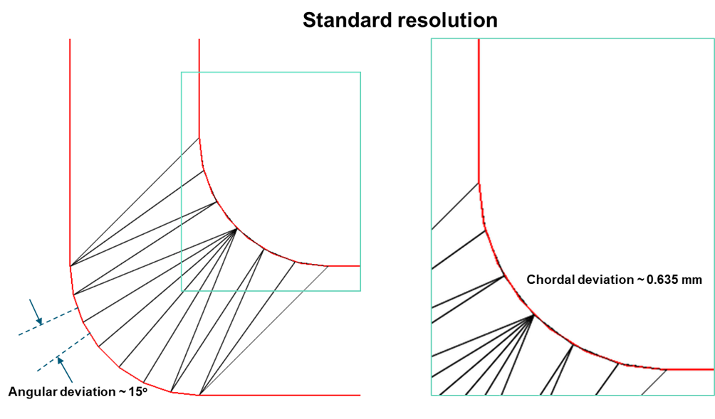
Figure 2. 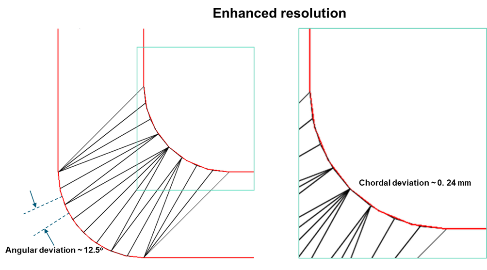
Figure 3. 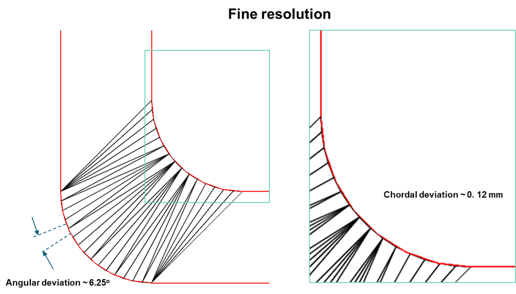
2. Units for Dimensionless CAD Files
This dropdown allows you to specify the physical units (for example, millimeters, inches) for CAD files that do not inherently contain unit information (dimensionless files). This is crucial for ensuring correct scaling of the imported geometry and subsequent physical properties (for example, material properties, loads).
3. CAD Reader Selection
SimSolid supports multiple CAD reading technologies to maximize compatibility and leverage specific format optimizations. The choice of reader can influence robustness, speed, and the fidelity of imported data.
- Parasolid (Inspire Reader)
-
This reader leverages the CoreTechnologie (CT) third-party libraries for initial CAD file parsing, then converts the geometry into the native Parasolid kernel representation. For native Parasolid files (.x_t, .x_b), it directly utilizes Parasolid libraries for reading and tessellation, ensuring high fidelity. For other formats, it uses the CT reader to convert to an intermediate format, then the Parasolid engine for final tessellation.
Tip: This option is generally robust for a wide range of CAD formats due to its reliance on a well-established geometric kernel for tessellation. - Parasolid and Spatial
-
This reader intelligently combines the strengths of both Parasolid and Spatial kernels. It is specifically optimized to use Spatial's reader and tessellation engine for CATIA, STEP, and Inventor files. For all other supported file formats, it reverts to the Parasolid-based reader described above.
Tip: It is highly recommended when importing CATIA, STEP, or Inventor files, as it utilizes a reader potentially better suited for the nuances of these formats. This can lead to improved import success rates and geometric integrity. - Legacy
-
This reader exclusively uses the CoreTechnologie (CT) reader for both reading and tessellation of all CAD formats. This option typically represents an older or more generalized import pathway.
Tip: Use this as an alternative if issues arise with the Parasolid or Parasolid and Spatial readers for a particular file format.
4. Import Geometry Type
This setting determines which types of geometric entities (solids, skins or both) SimSolid will process during import. Understanding the distinction is crucial for preparing your CAD model.
- Solids and skins (Default)
-
This option attempts to import both watertight solid bodies and skins. When importing skins, SimSolid will attempt to identify and import, which can be later inflated by assigning uniform thickness.
- Solids only
-
This option strictly filters out and ignores all surface (skin) geometries during import. SimSolid will only process and attempt to import watertight solid bodies. This will attempt minor repairs on near-watertight solids but will discard any geometry with large openings or non-manifold edges that prevent it from being a closed volume.Tip: This is recommended when you are certain your CAD model should only contain solid components for analysis, and you want to explicitly exclude any accidental or non-structural surface data.
- Skins only
-
This option imports only surface geometries, completely ignoring any watertight solid bodies. This includes single surfaces, collections of surfaces, and parts with missing faces that prevent them from being closed volumes.
Tip: This option is particularly valuable for modeling thin-walled structures where the original CAD may provide only a mid-surface or a single boundary surface (for example, sheet metal, plastic housings). After import, you can use Create sheets option (found in the Assembly tools) to assign a specified physical thickness to these imported surfaces. This effectively transforms the surface into a volumetric shell or a representation of a solid body with a defined thickness.Important: SimSolid can import skins from most CAD formats (assemblies or part files), with the exceptions of plugin files and STL formats.
5. Import Materials
This feature streamlines the assignment of material properties by attempting to read material information embedded within the CAD file's metadata.
SimSolid actively searches for specific metadata attributes within the CAD file that are designated as containing material property names. If a retrieved name string exactly matches a material definition within the user's current SimSolid material database, those corresponding material properties will be automatically applied to the imported part.
- Limitations
-
SimSolid's ability to read CAD material metadata is specific to certain CAD formats. Currently, this functionality is supported for CATIA, NX, and JT files only.
- Handling Unmatched Materials
-
If a material name from the CAD metadata is not found in the SimSolid material database, a dialog will appear, prompting the user to manually select an alternative material from the existing SimSolid database. This is particularly useful for assemblies with multiple distinct materials, allowing for efficient assignment.
Figure 4. 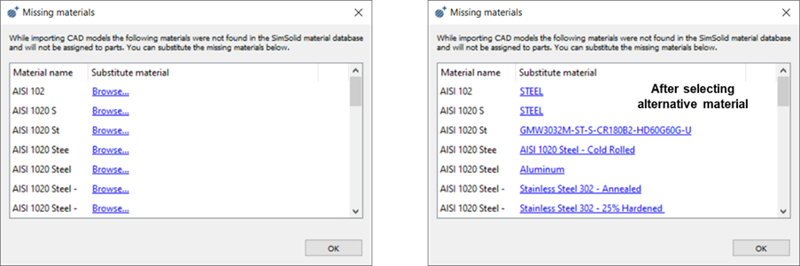
- Custom Material Database
-
For comprehensive and consistent material assignment, it is highly recommended to define a custom SimSolid material database that mirrors the material definitions used in your CAD system. Refer to the Define Custom Material Database topic in SimSolid's help for detailed instructions on how to achieve this. This reduces manual intervention and ensures material accuracy.
6. Custom Metadata Attributes
This setting allows users to specify additional, non-standard metadata attributes that SimSolid should search for within the CAD file. You can list any custom metadata attributes desired in the text box. SimSolid will search in the order listed and these values will take precedence over any internal default values.