Rotordynamic Analysis
Theory
Rotordynamics is a structural dynamic analysis on the behavior of rotating machinery, such as shafts, turbines, and compressors. The analysis framework incorporates key theoretical concepts to accurately model and predict the dynamic response of rotors. When a component within the structure rotates, additional forces like the gyroscopic force and circular damping force act on it.
It is important to determine the effects of rotating components on the system. The natural frequencies of a system usually change, if gyroscopic forces act on the model due to a rotating component. Circulating damping forces due to rotating components can lead to system instability. These forces are a function of the frequency of rotating component. The rotating components of the structure are the shafts on which gears are mounted. The design of the rotors and their angular frequencies can affect the dynamic response of the structure. Any design will most likely lead to asymmetrical mass distribution about the rotor axes. This unbalanced mass, even if it is not significant, can result in deflection of the rotor depending on various factors. The magnitude of these deflections will be augmented when the rotating speed of the shafts equals the natural frequency of the structure (resonance) and can lead to catastrophic failure of the system.
Rotordynamics analysis can be classified based on the relationship between the whirl speed (the frequency at which the rotor center of mass orbits the axis of rotation) and the rotor spin speed (Ω).
Modal rotordynamics analysis with SimSolid, often through complex eigenvalue analysis, primarily employs the Asynchronous approach to calculate the forward and backward whirl frequencies as a function of the rotor speed. This allows for the construction of the Campbell diagram. The whirl speed is independent of the rotor spin speed (ω≠Ω). This approach is used to determine the natural whirl frequencies (eigen frequencies) of the system at various spin speeds, which is essential for plotting a Campbell diagram to identify the critical speeds and investigating potential instabilities.
Coriolis Effect
- n the rotating rotor, any radial velocity (Vr) of a point mass due to vibration generates a tangential Coriolis force, and similarly, a tangential velocity (Vt) generates a radial Coriolis force.
- This effect is captured by the gyroscopic matrix in the equations of motion and is responsible for coupling the motion in the x and y directions, leading to the distinct forward and backward whirl modes.
Stress Stiffening (Centrifugal Stiffening)
- As the rotor spins, the centrifugal force induces tensile stress in the rotor structure.
- This tensile stress increases the effective stiffness of the rotor, leading to a slight increase in the natural frequencies (whirl frequencies) as the spin speed increases. The SimSolid rotordynamic formulation accounts for this effect to provide a more accurate prediction of critical speeds, especially at high rotational speeds.
Frames of Reference
SimSolid typically utilizes the Rotating Frame of Reference for its rotordynamic analysis formulation. The coordinate system (x, y, z) rotates with the rotor at its spin speed (Ω). In this frame, the geometry is stationary, which can simplify some aspects of modeling, such as unbalance. This choice simplifies the modeling of rotor geometry and allows for a more straightforward inclusion of the rotational effects in the equation of motion.
Campbell Diagram
- It is a plot of the natural whirl frequencies (ω in rad/s or Hz) of the rotor system (the eigen frequencies) against the rotor spin speed (Ω in rad/s or Hz).
- Critical speeds are identified by the intersection points of the natural
frequency lines with the rotor speed line ( Ω = ω or 1X line) and its
multiples (for example, 2X line).
- The 1X intersection is the most important, indicating where the
whirl frequency matches the excitation frequency from mass
unbalance, leading to resonance and potentially excessive
vibration.
Figure 1. 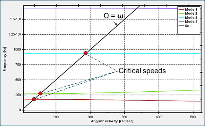
- The 1X intersection is the most important, indicating where the
whirl frequency matches the excitation frequency from mass
unbalance, leading to resonance and potentially excessive
vibration.
Damping Diagram
- It plots the damping (typically, eigenvalue (real) upon eigenvalue (imaginary), which is then multiplied by 2) against the rotor spin speed (Ω).
- Stability assessment:
- Positive damping means the rotor system is stable, and any vibration will decay over time.
- Negative damping means the rotor system is unstable, and vibration amplitudes will increase over time, potentially leading to failure. This is often associated with the onset of instability mechanisms like oil whip or internal friction.