
Guiders
Designate parts on the model as guiders.
Designate Guiders
Designate one or more parts in your model geometry as guiders to direct the injection of foaming materials into a foam part.
-
Click the Tooling icon.

-
In the Tooling sub-ribbon, click the Guider icon.

- In the guidebar, click the Guider button. Select a part in the model to designate it as a guider.
-
Use the Microdialog to define the Thickness, Conductivity, and Slip Factor of
the Guider.
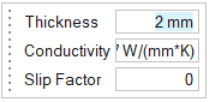
Thickness defines the average thickness of the guider part's outer wall. In most cases, the default value of 2 mm will be correct.Conductivity defines the thermal conductivity of the guider part. In most cases, the default value will be correct.
Slip Factor defines how easily the material flows through the guider. In most cases, the default value of 0 will be correct, however if the guider has many curved surfaces, a value of 0.2 may yield better results. Values less than -1 or greater than 1 are not valid.
- In the guidebar, click the Outlet button. Select a surface on the guider component to create an outlet.
- In the guidebar, click the Nozzle button. Select a surface on the guider to create a nozzle.
-
Use the microdialog to define the nozzle's Material, Material Temperature,
Nozzle Radius, Mass Rate, Start Time, and Holding Time.
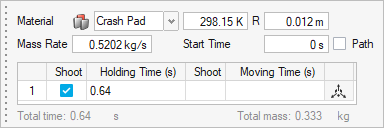
Note: The Path checkbox will be disabled, since guiders are stationary. - Repeat steps 3 through 7 for each guider part in the model.
- Right-click and mouse through the check mark to exit, or double-right-click.