
Pouring Cup Test
Use the basin (cup) icon to run an optional pouring cup test to evaluate a material that you want to assign to your model for a foaming simulation.
The pouring cup test shows you how parameters such as temperature and fill percentage can determine the foaming behavior of a material relative to a particular mold shape. The simulated expansion of the foam can help you determine the optimal conditions and material amounts to use in the physical manufacturing of the foam part.
The pouring cup test is conducted separately from the foam part setup and simulation. Run a pouring cup test before loading your foam part model, otherwise you will be prompted to close your model.-
Hover over the Foam Part icon and click the
Pouring Basin satellite icon.

The default basin appears prefilled at 20%.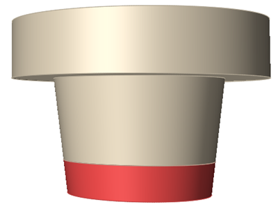
-
Use the microdialog options to define the basin and material, and to run the
test.
Microdialog option Description 
Select a shape for the pouring basin, then expand the dialog and enter the dimensions for the basin: - For the cylinder, enter a radius and height.
- For the cone, enter a bottom radius, top radius and height.
- For the cube, enter a length, width and height.
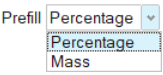
Specify the amount of material in the basin at the start of the test either by mass (in units) or volume (as a percentage of the basin capacity). The default prefill is 20% of the basin's capacity. 
Click the View Materials button to open the Materials
dialog and review the material properties of your selected
material. You can also edit, import, export and assign
materials from this dialog.
Select a material for the pouring cup test. You can also assign a material from the Materials dialog. 
Enter the initial temperature for the selected foaming material. End time condition Enter the desired duration of the test in seconds. The default value of 300 seconds will usually be sufficient. Environmental HTC Enter the environmental heat transfer coefficient for the material. Environmental Temperature Enter the ambient temperature for the simulation. Sensors 
Click the to place one or more virtual
sensors in the pouring cup, if desired. The sensors will
show data from their location during the simulation.
Shape options 
Click the chevrons to reveal fields that control the dimensions of the pouring cup. Height Change the height of the pouring cup basin. Overflow Height Change the height of the overflow region. Radius Change the pouring cup's radius (cylindrical pouring cups only). Bottom Radius Change the pouring cup's bottom radius (conical pouring cups only). Top Radius Change the pouring cup's top radius (conical pouring cups only). Length Change the pouring cup's length (squared pouring cups only). Width Change the pouring cup's width (squared pouring cups only). 
Click the Run button to run the pouring cup
test.Material Characterization Check the checkbox to enable the Material Characterization process. Configure Click to open the Material Characterization window. Note: You will need data gathered from a real-world pouring cup experiment to use the Material Characterization feature. - Select the completed run in the Run Status window.
-
Select a Stage and Result Type in the Analysis Explorer and review the
results.
The following examples show results for the Crash Pad material in a cone basin with default settings.
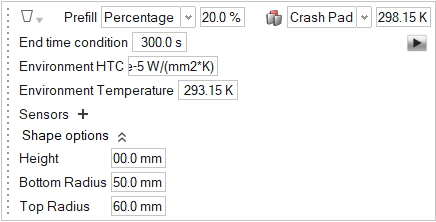
Figure 1. Air pressure results for the defects stage 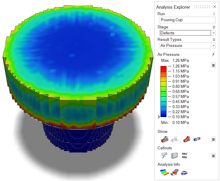
Figure 2. Polyol [mgKOH] results for the foaming stage 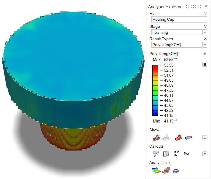 Note: To view data from sensors, select the Callouts
 button in the Analysis
Explorer.
button in the Analysis
Explorer.
Material Characterization
Use data from your own physical pouring cup experiments to refine the results for PolyFoam's virtual pouring cup test and other simulations.
Material Characterization Window
Before you use the Material Characterization window, you will need to gather data from a real-world pouring cup experiment. In your experiment, use one of the materials described in the Materials Database, or one of the customized materials in My Materials. See Create/Edit Materials for details.
When the real-world data is available, enter it into the Material Characterization window.


If the curves do not align, you can adjust the Material Characterization settings and re-run the analysis. After running a material characterization analysis where simulation results match experimental results, future simulations for that material will be much more accurate.
| Window Option | Description |
|---|---|
| Material Type |
Note: This field is not directly
controllable. Either "Soft Material" or "Rigid Material"
will appear, depending on the material selected in the
Pouring Cup microdialog.
|
| Name | Enter a name for your modified material. |
| Polyol : Isocyanate | Enter the parts by weight of isocyanate per 100 parts of polyol. Generally, as this number increases, the finished product will be more rigid. Other additives can also affect the properties of the product. |
| Water | Enter the parts by weight of water per 100 parts of polyol. Usually, more water in the mixture results in quicker and greater expansion. |
| OH Value | Enter the milligrams of KOH per gram of other material. |
| NCO | Enter the percentage by weight of unreacted isocyanate groups in the material. |
| Blowing Agent | Enter parts by weight of blowing agent per 100 parts of
polyol. Note: This field appears only for
rigid materials. |
| Blowing Agent Boiling Point | Enter the blowing agent's boiling temperature. Note:
|
| Quick run | Limit the number of simulation iterations to the number
specified in the Preferences. The default value of 200
iterations will otherwise apply. Note: Visit to change the iteration limit. |
| Base Material |
Note: This field is not directly
controllable. To change the Base Material entry, you must
select a different material in the Pouring Cup microdialog.
|
| Gelling E | Enter the lower and upper limit of the gelling activation energy for the material. |
| Gelling dH | Enter the lower and upper limit of the gelling latent heat. |
| Chemical Blowing E | Enter the lower and upper limit of the chemical blowing activation energy for the material. |
| Chemical Blowing dH | Enter the lower and upper limit of the chemical blowing latent heat of the material. |
| Physical Blowing E | Enter the lower and upper limit of the physical blowing
activation energy for the material. Note: This field appears only for rigid materials. |
| Physical Blowing dH | Enter the lower and upper limit of the physical blowing
latent heat of the material. Note: This
field appears only for rigid materials. |
| CO2 Saturation | Enter the lower and upper limit of the CO2 saturation of the material. |
Import Data  |
Import height curve and temperature curve data from a
formatted .csv or .txt file. Note:
|