Open the
PollEx_PCB_Additive_Sample_r<revision
number>.pdbb file from
C:\ProgramData\altair\PollEx\<version>\Examples\Modeler\Additive.
From the menu bar, click Tools > Worksheet Planner.
Load Template Format file.
Click Load.
Select the
C:\ProgramData\altair\PollEx\<version>\Examples\Modeler\Additive\WorksheetPlanner_Sample.ppwt
file and click Open.
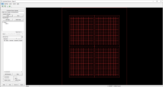
A page is automatically created in the left page list, and a
sheet form is displayed on the screen. Figure 1.
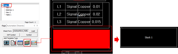
Create Page Template.
Click the in the Add Template Type section.
Click and drag in the right screen to create a Worksheet Planner
Sample.
Figure 2.
Click the View1 screen.
The data is displayed on the screen. Figure 3.
Layer Setting.
Set the Layer in the Layer tab.
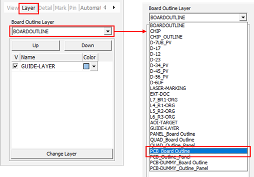
In the Layer tab, click Change Layer.
The Select Layer From List dialog
opens.
In the Select Layer From List dialog, enable the
GUIDE-LAYER checkbox and click
OK.
Select PCB_Board Outline from the Board Outline
to display the layer on the screen.
Figure 4.
Add Mark.
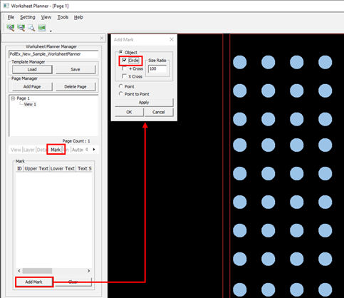
Click Add Mark in the Mark Tab.
The Add Mark dialog opens.
In the Add Mark dialog, enable the
Circle checkbox.
Figure 5.
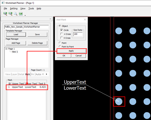
Select the pad on the screen, click Apply, and
click OK.
Figure 6.
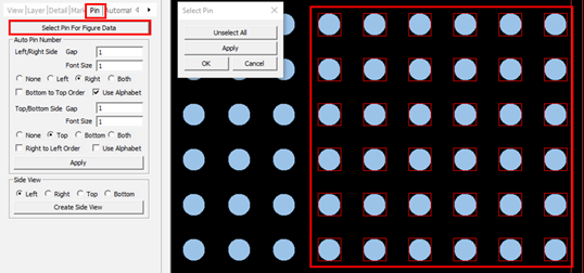
Mark Pin Name.
In the Pin tab, click Select Pin For Figure
Data.
The Select Pin dialog opens.
Using the mouse, drag and select the pin area to create a pin number on
the right.
Figure 7.
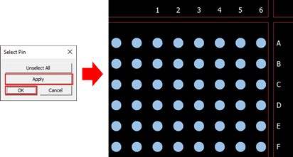
Click Apply and click OK.
The Pin Name is displayed on the screen. Figure 8.
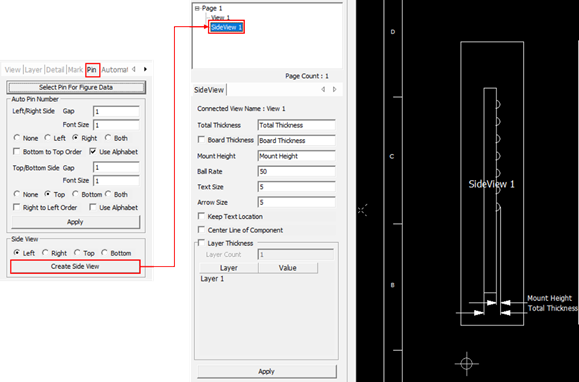
Create Side View.
Click the Create Side View.
Side View is automatically created in the Page
list.
Click Side View in the list.
Side View is displayed. Figure 9.
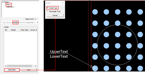
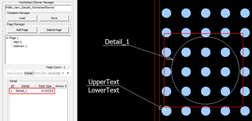
Define details.
Click View 1.
From the Detail tab, click Add Detail.
The Detail dialog opens.
In the Detail dialog, select Circle
Type and set the areas on the screen by dragging the
target area.
Figure 10.
The detail areas set on the screen are displayed. Figure 11.
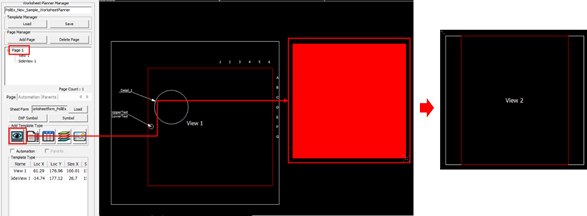
Select Page 1, click , and drag the mouse to create another view
area.
Figure 12.
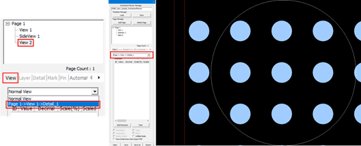
Select View2 and select the View Type detail_1
in the Layer Tab.
The detail area is displayed on the screen. Figure 13.
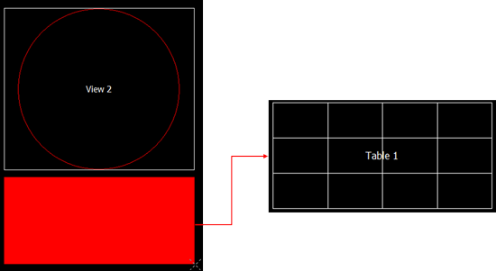
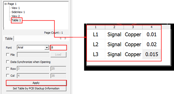
Create table.
Select Page1 and click .
The Insert Table dialog opens.
In the Insert Table dialog, set the number of
columns and rows to be in the table, and click OK.
Figure 14.
Drag the mouse on the page screen to create a view area.
Figure 15.
Select a table from the list and enter the stack information in the
table.
Change the font size of the entered value and click
Apply.
Figure 16.
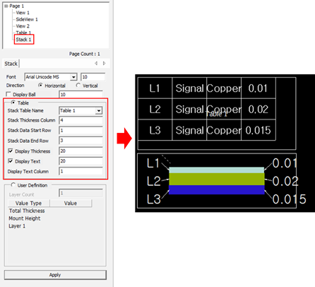
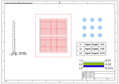
Create Stack.
Select Page 1 and click .
Drag the mouse on the screen to create another view area.
Figure 17.
Select a stack from the list and set the display value of the
stack.
Specify the table to be used for the stack as Table1 and set the stack
information. The stack is displayed on the screen.
Figure 18.
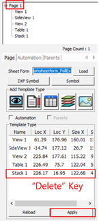
Delete created lists.
Select a list for the templated type list in Page 1, and press
Delete.
Click Apply to delete the selected type.
Figure 19.
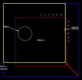
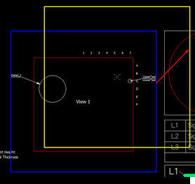
Resize the area.
Select the page to change and click each area on the right to adjust
the size of the area.
The selected area is indicated by a blue line. The size change is
increased after selecting the corner part of the rectangular area. In
the changeable state, the line of each area is displayed in yellow.
Press Esc to cancel the
operation. Figure 20.
Move the Area Position.
Select the page to change and click each area on the right to move the
area. The area selected is indicated by a blue line.
Click the white box and press Enter.
Click the target area. The area moves to the selected location. In the
moveable state, the line of each area is displayed in yellow. Press
Esc to cancel the
operation.
Figure 21.
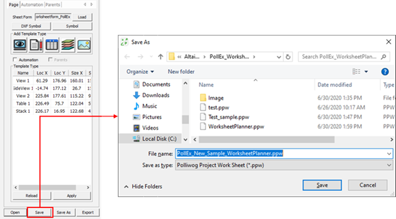
Save and Load Worksheet Planner File.
When saving, the file name is saved as the sample file name. It is saved in
the location where the sample file is located. Figure 22.
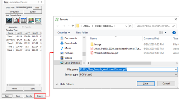
Export Worksheet Planner File.
You can export the Worksheet Planner file to PDF format. Figure 23. Figure 24.

 in the Add Template Type section.

 .
The Insert Table dialog opens.
.
The Insert Table dialog opens.
 .
.