CP Tutorial
PollEx CP (Cross Probe) is a software used to compare two different designs and find the differences.
Target designs can be PCB design and PCB design, PCB and schematic design, or schematic and schematic design. They can also be PCB, schematic, and BOM.
-
Compare Two PCB Design Data.
-
Select PCB, click
 for PCB1, and select PDB binary file.
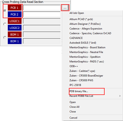
Figure 1. -
For PCB 2, select the
PollEx_CP_Sample_PCB_T2_r<revision
number>.pdbb file from
C:\ProgramData\altair\PollEx\<version>\Examples\Modeler\CP.
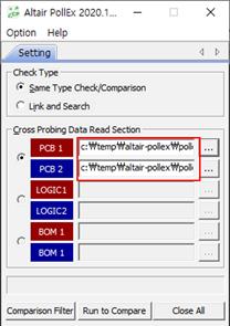
Figure 2. -
Click Run to Compare.
Highlighted in purple means that an object exists in only one design. The others (without highlight) means that an object exists in both designs.
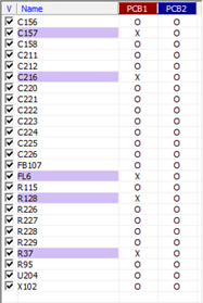
Figure 3. -
Click Open All and click Reset
Window to check the differences between the
designs.
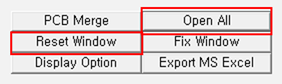
Figure 4.
-
Select PCB, click
-
Comparison between two Schematic Designs.
-
Select LOGIC and click for LOGIC1.
-
For LOGIC2, select the
PollEx_CP_Sample_Logic_T2_r1.0.sdbb file from
C:\ProgramData\altair\PollEx\<version>\Examples\Modeler\CP.
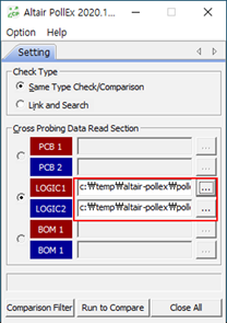
Figure 5.
-
Select LOGIC and click
-
Result Comparison.
Highlighted in purple means that an object exists in only one design. The others (without highlight) means that an object exists in both designs.
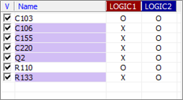
Figure 6.-
Click C106.
C106 exists in LOGIC2 only. In the LOGIC2 window, the component located area automatically zooms-in. In the LOGIC1 window, there is no C106.
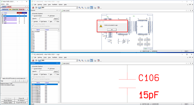
Figure 7. -
Click C103.
C103 exists in both schematic designs, but there is a difference of part name in each design.
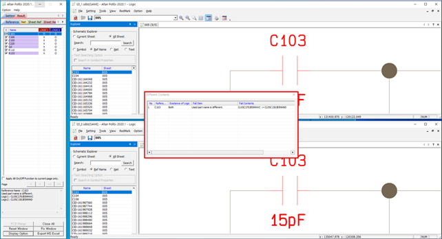
Figure 8. -
Click the Net tab and click
MCU_XTORTC.
MCU_XTORTC exists in both schematic designs, but there is a difference of connected Pin in each design.
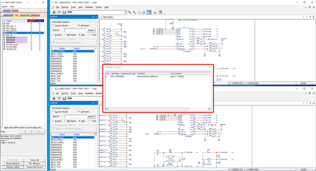
Figure 9. -
Click Export MS Excel and select
Basic Excel Formaton.
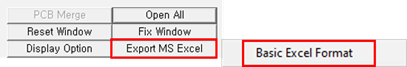
Figure 10.
-
Click C106.
-
Comparison between PCB, Schematic Design, and BOM.
-
Select Link and Search.
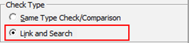
Figure 11. -
Select PCB and click for PCB1.
-
Select LOGIC and click for LOGIC1.
-
Select the PollEx_CP_Sample_Logic_T1_r1.0.sdbb
file from
C:\ProgramData\altair\PollEx\<version>\Examples\Modeler\CP.
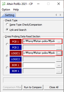
Figure 12.
-
Select Link and Search.
-
Result Comparison.
Highlighted in pink means that an object exists in only one design. Highlighted in yellow means that an object exists in both designs, but there is different information. The others (without highlight) means that there is no difference.
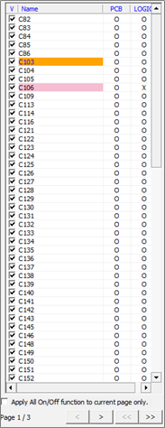
Figure 13. -
Three Point Comparison.
- Select Link and Search.
-
Select PCB and click for PCB1.
- Click All Job Open.
- Select PollEx_CP_Sample_PCB_T1_r<revision number>.pdbb, PollEx_CP_Sample_Logic_T1_r1.0.sdbb, and PollEx_CP_Sample_BOM_r1.0.bdbb from C:\ProgramData\altair\PollEx\<version>\Examples\Modeler\CP.
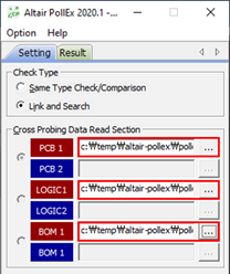
Figure 14. -
Result Comparison.
Highlighted in pink means that an object exists in only one design. Highlighted in yellow means that an object exists in both designs, but there is different information. The others (without highlight) means that there is no difference.
-
Select C237 for BOM and right-click
Link All (Only Ref).
The selected part displays on PCB, Logic, and BOM.
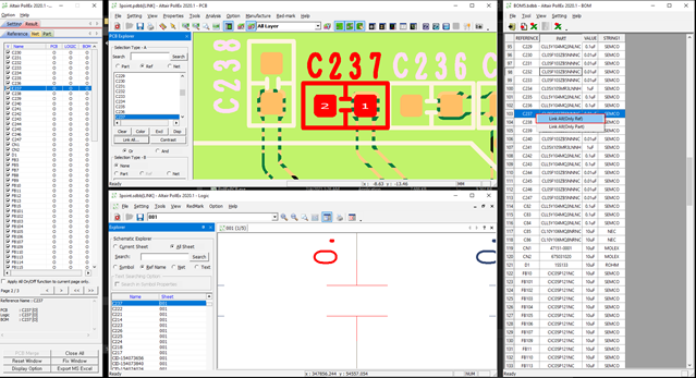
Figure 15.
-
Select C237 for BOM and right-click
Link All (Only Ref).
-
Export Result to MS Excel.
-
Click Export MS Excel and select
Basic Excel Format.
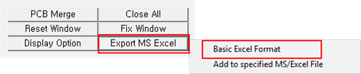
Figure 16.
-
Click Export MS Excel and select
Basic Excel Format.