Altair PollEx 2022.1 Release Notes
This section contains all the changes for the 2022.1 release for PollEx.
Highlights
- PollEx documentation is now available via Online Help.
- Added a new AOI/AXI feature under the Placement category in DFM. Use to
check components on the board that obstruct the field of vision by the
height of specific parts.
Figure 1. 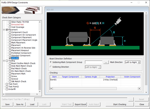
- In DFM, DFA, and DFE, you can change the pass/fail mark in the User Defined
Excel Format Report. During the first step, change this in the Pass/Fail
Mark Definition area. Note: The example below is from PollEx DFM.
Figure 2. 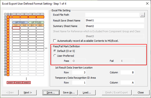
- Added a part comparison feature for different variants on the PCB.
Figure 3. 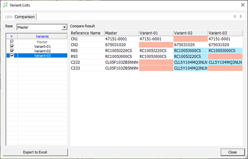
- Added a PCB design comparison feature for different variants in CP.
Figure 4. 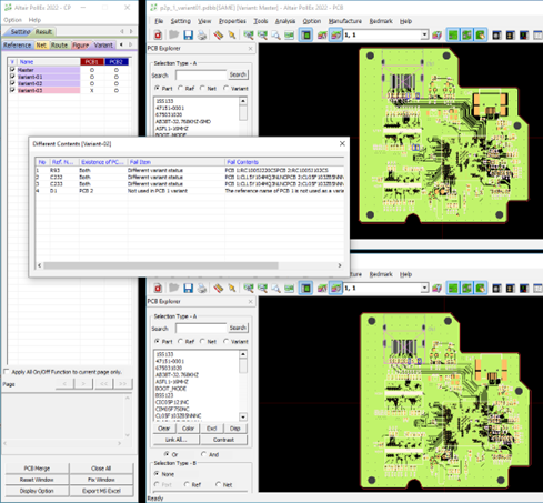
- Improved display simulation model information of passive components in the
Net Topology Analyzer of SI. When using a simulation model such as
Spice/S-parameter other than the RLC model, value information is not
displayed.
Figure 5. 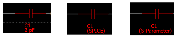
- Added a function that automatically measures basic timing in SI Waveform
Viewer such as Positive/Negative peak, Peak to Peak, overshoot/undershoot,
and so on.
Figure 6. 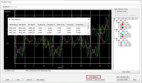
- Added a function to save and load waveform data in each window of
Time-Domain and Frequency-Domain when performing Radiated Emission, and
compare various case analysis results through a what-if simulation.
Figure 7. 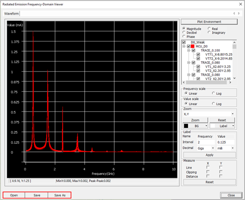
- Added a feature to the network parameter mode conversion for 4-port
S-parameter in the Network Parameter Viewer dialog. To check the S-parameter
against industry standard compliance plots, the single-ended measurements
need to be converted to a mixed-mode matrix.
Figure 8. 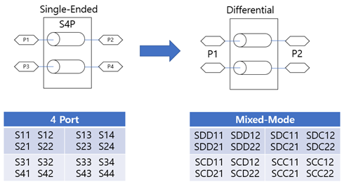
Figure 9. 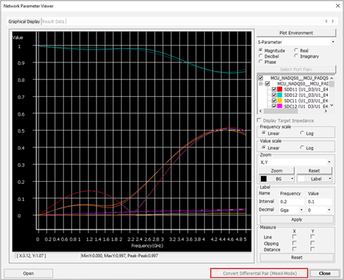
- Added a menu to the set component placement layer in the Net Topology
Analyzer.
Figure 10. 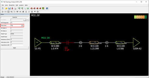
- Modified to support MCP (Multi Chip Package) structure in SI like eMMC that
describes the package parasitic in EBD file within PollEx. By registering
MCP models in the Properties/Parts menu, MCP structure IC analysis is
possible.
Figure 11. 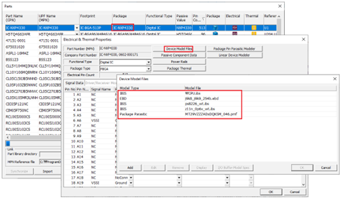
- Modified the source pin setting method in PI. In the Select Power
Net Pins dialog of PI, the structure is changed so that the
source/load pins can be set in the same dialog.
Figure 12. 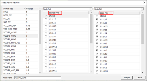
- Added a composite power net in PI. When the power net is connected to each
other as a series passive component, the function to composite it has been
added. In the sample below, VCC1P0_CORE is connected to VCC1P0_USB through
FB113 passive component and supplies power to CN2-1.
Figure 13. 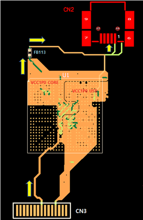
In this case, after selecting the power net VCC1P0_USB to connect, select the mode as Composite Net. After, the passive component connected to this net is displayed as FB113 in the list. After selecting this passive component, select Source Pin and Load Pin.
Figure 14. 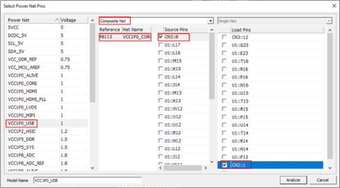
Then, the Composited Power Net is displayed on the PIA dialog as shown in the figure below. PDN and IR-Drop Analysis can be performed.
- Added a function to import NTF information in SI Explorer. In addition to the corresponding Net Topology Model, PCB Layer Stackup, Transmission Line Model, and VIA model are imported together. From the menu bar, click
- Added a feature to multi-load when creating Net Topology in SI and SI
Explorer. You can create the desired multi-load net topology by adjusting
the Load Count and Branch Depth Count parameters.
Figure 15. 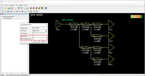
- Added a feature to export part libraries (symbols and footprints) to Cadence Allegro, OrCAD Capture CIS. From the menu bar, click
- Added a feature to export part libraries (symbols and footprints) to Zuken CR-5000 and CR-8000. From the menu bar, click
New Features
- PollEx Modeler
- PCB
- Added a part comparison feature between variants.
- Added a feature to handle variant data when saving as a project.
- Added a Solder-Resist item in the Material library menu.
- Added a feature to change the coordinates of the DXF layers.
- PollEx Verification
- DFM
- Added a new checking item for the AOI/AXI.
- Added a function in the BGA item to check the clearance between the laser via and other objects.
- Added a feature to link the DFM Excel results to ECAD tools.
- PollEx Analysis
- SI
- Added the Analyze Impedance button to Properties/Layer Stack dialog to perform impedance analysis.
- Added a function to import NTF to SI explorer. Use to import Topology and Part information created in PollEx SI.
- Added a function to automatically measure basic timing such as Positive/Negative peak, Peak to Peak, overshoot/undershoot, and so on in SI's Waveform Viewer.
- Added a function to save and load waveform data in each window of Time-Domain and Frequency-domain when performing Radiated Emission.
- In the case of 4-port S-parameter in the Network Parameter Viewer dialog, the mode conversion function is added.
- Added the ability to perform SI network analysis with command lines.
- PollEx UPE
-
- Add an option to display a currency in the part price setting.
- Add a feature to import or export UPF library XML format.
- Add a feature to export footprint library to Cadence Allegro.
- Add a feature to export symbol library to Cadence OrCAD Capture CIS.
- Add a feature to export footprint library to Zuken CR-5000/CR-8000.
- Add a feature to export symbol library to Zuken CR-5000/CR-8000.
Enhancements
- PollEx Modeler
- PCB
- Enhanced the measure option of the Object to Object.
- PollEx Verification
- DFM
- Added a Measure Base option in the PCB Outline Spacing, the Routing Slit, and the Intermediate Pattern items that set the overlapped area of a pad and a solder mask (Pad+Solder Mask Overlap).
- Added an option in the PCB Outline Spacing, the Hole Distance, the Via Spacing, and the Net to Net items to check Laser Via clearance.
- Added an option in the Copper Keep-out around Pad item to check the same net and the other net separately.
- Added an option in the Copper Keep-out around Pad item to check opposite side of target component and to check route pattern and via clearance.
- Added an option in the Placement Keepout item to exclude specific nets from the via and route pattern clearance checks.
- Added an option in the Keep Out Pattern item to check only specified nets using string filter.
- Added an option in the Pair Comp item to check the opposite side of the target component.
- Enhanced the Pad to Net item to check the route pattern connected to the NC Pins.
- Added a Pass/Fail Mark Definition option in the User Defined Excel Format Setting dialog to use User-Preferred string.
- Added a scroll bar for all checking items.
- PollEx Analysis
- SI
- Modified to display the model type when the passive component value is displayed in the Net Topology Analyzer (RLC, Spice, S-parameter).
- In SI explorer, layer stackup is modified so that the user can change it.
- Modified to enable multiple selection of pins in the Select Pin List dialog during setup work to select the default buffer model in the Part menu of SI.
- The progress bar displayed during analysis is changed from displaying icon images to displaying step-by-step progress.
- The adjustment range of the rising/falling time was expanded to 0.1ps.
- In the result window after performing Radiated Emission, the same net is modified to use the same color.
- Modified so that the placement layer can be selected when adding a component in the Net Topology Analyzer.
- Modified to analyze the topology of multiple nets in the Net Topology Analyzer of SI Explorer.
- PollEx UPE
-
- Add an option to define the manufacturer preference.
- Add an option to select the default value in the package wizard.
- Add an option to define the currency of part price.
- PollEx Interface from ECAD
- PADS
- Improved test positioning to match with PADS data.
Resolved Issues
- Fixed a bug where NPTH holes were missing when importing ODB++ data.
- Fixed a bug that mishandled a thermal relief pad from the Altium Designer.
- Fixed a bug that there is no Padstack connection information of the pin in ODB I/F.
- Fixed a bug that board outline and hole could be selected when exporting to PDF in PCB.
- Fixed a bug that the synchronize feature was not working when the unit is not millimeter in UPF.
- Fixed a bug that navigated to the wrong zoom area of Logic data in CP.
- Fixed a bug that error images did not appear intermittently when exporting a report in CP.
- Fixed a bug that the assigned padstack name is changed after removing other padstack in UPE.
- Fixed a bug that handled step information as an exception when the x and y sizes of the truncated section is 0 when using an automatic pin setting with the footprint function in UPE.