Lead
Lead to Hole
Checks the clearance between the DIP type component’s lead and hole. If there is not
enough clearance, it results in soldering defect.Figure 1.
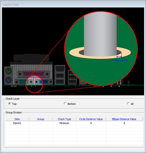
- Check Layer: Select checking target layer.
- Item: Input item name.
- Group: Specify the target group name. You can select the group from the list. x.
- Check Type
- Minimum: Set the minimum clearance between Lead and Hole.
- Maximum: Set the maximum clearance between Lead and Hole.
Figure 2. 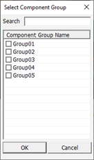
- Circle Clearance: Enter the clearance for circular hole.
- Ellipse Clearance: Enter the clearance for ellipse hole.
Lead Length
Checks the length of DIP type component’s lead. If it is much longer than the allowable length, PollEx DFA can detect it.
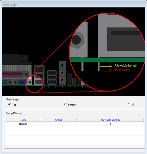
- Check Layer: Select checking target layer.
- Item: Input item name.
- Group: Specify the target group name. You can select the group from the
list.
Figure 4.
- Allowable Length: Input allowable lead length.
Package Pin & Footprint
Checks the distance between package lead and footprint pad. Inspects toe-print, heel-print, and side distance.
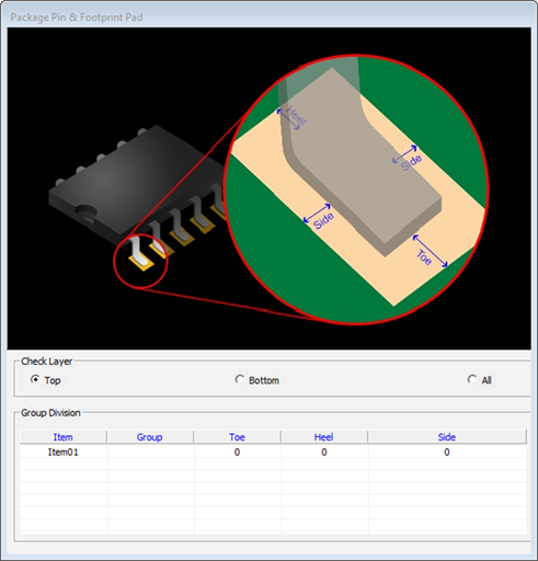
- Check Layer: Select checking target layer.
- Item: Input item name.
- Group: Specify the target group name. You can select the group from the
list.
Figure 6.
- Toe: Distance from package leads edge to footprint pad’s outer edge. If the measured distance is smaller than the given value, it fails.
- Heel: Distance from package leads edge to footprint pad’s inner edge. If the measured distance is smaller than the given value, it fails.
- Side: Distance from package leads edge to footprint pad’s side edge. If the measured distance is smaller than the given value, it fails.