Package Base Input

Define shape and size of package body and pins.
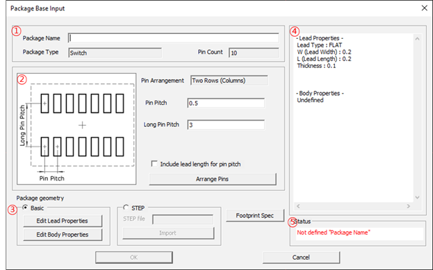


Figure 1.
  1. Package Information: Define information of the package.
    1. Package Name: Define the package name.
    2. Package Type: Display the package type.
    3. Pin Count: Display the pin counts of the package.
  2. Pin Arrangement Information: Display and edit the pin arrangement.
    1. Pin Arrangement: Display the pin arrangement type.
    2. Pin Pitch: Define the pin pitch of the package (short side).
    3. Long Pin Pitch: Define the pin pitch of the package (long side).
    4. Include lead length for pin pitch: When setting the pin pitch, include the pin length.
    5. Arrange Pins: Define the pin arrangement of the package. Refer to Pin Arrangement.
  3. Package geometry: Define the package geometry.
    1. Basic: Use the basic package shape editor to define the package geometry.
    2. Edit Lead Properties: Define the package pin shape and size.
    3. Click Edit Lead Properties to edit the pin shape.

Type 1: Basic

Define the package shape using the basic shape already registered.
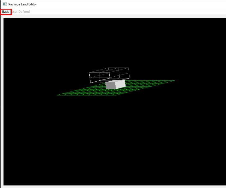


Figure 2.
  1. In the Package Lead Editor dialog, click the Basic tab.
  2. Lead Shape View: Display the package pin lead shape in 3D view.
  3. Lead Information: Select and show package pin lead shape.
    1. Lead Type: Select the package pin lead type.
      Supported basic shapes are JBEND, BUTT, Reverse BUTT, FLAT, GULLWING, GULLWING-A, Round GULLWING, WRAPAROUND, BAR, Round BAR, Round BAR-A, Round BAR-B, Round, BAR-C, BALL, DIP, DIP-A, DIP-B, DIP, Kink DIP-A, Round DIP, DIP-A, CBEND, J Inverted and WIRE.
    2. L (Lead Length): Define the pin lead length.
    3. W (Lead Width): Define the pin lead width.
    4. Thickness: Define the pin lead thickness.
      The size dimension format is changed depending on the pin lead types.
  4. Reverse: Reverse the edited package lead shape.

Type 2: User Defined

Define the package shape using free style editor.
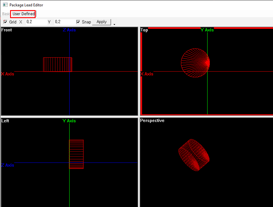


Figure 3.
  1. In the Package Lead Editor dialog, click the User Defined tab.
  2. Grid: Define the grid gaps.
    1. X, Y: Define the grid X, Y gaps.
    2. Snap: If selected, picking point is snapped on grid.
    3. Apply: Apply the defined grid settings.
  3. Display and Edit Window: Display and edit the package pin lead shape.
    Front, Top, Left side view and Perspective view are supported.
  4. Select an object to display the properties in the front or top or left side view window.
  5. In the Property tab, display and edit the package pin properties window.
    The property formats are changed depending on the package shapes.
  6. In the Position tab, display and edit the position and angle of the object.
  7. To move an object, select the Shift check box.
    1. Enter the coordinates in the dialog and click Shift to move the object to a defined coordinate.
    2. Click Reset to cancel the entered coordinate.
  8. To rotate an object, select the Rotate check box.
    1. Enter the angles and click Rotate to rotate to a defined angle.
    2. Active View: Select the base view window to rotate the object.
    3. Click the arrows to rotate the object.
    4. Define Angle: Define the angle per each click of an arrow.
  9. Edit Shape Function: Edit the pin shape with supported shape.
    Supported shapes are cuboid, cuboid with inner hole, cylinder, cylinder with inner hole, pyramid, sphere, 3D Ellipse, pillar, and lead. If there is not any shape matched with the pin then user can select to edit an arbitrary shape.
  10. Click Edit Body Properties to define package body shape and size.
    1. Body Shape: Select the package body shape.
      • Arbitrary: Define the package type as an arbitrary shape and it can be edited by Edit Package Body function in the Package tab.
      • Cuboid: Define the package type as a cuboid shape. You can generate a package body with its size.
      • Cylinder: Define the package type as a cuboid shape. You can generate a package body with its size.
  11. STEP: Import a STEP format file for package lead shape. Click Import and select the STEP file to import.
  12. Footprint Spec: Define the pad size of footprint.
    Define the minimum and maximum size of toe, heel, side of the pad and the mount height of the package.
  13. Property View: Display the properties of package lead and body.
  14. Status: Display the package lead generating status.