Define Package Dimension
-
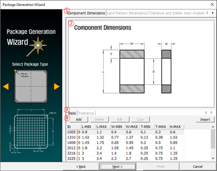
Input Items: Select items tab for input dimensions.
-
Land Pattern Dimensions: Tab for entering the pad size dimensions of
the package. Only for supported packages.
Figure 2. 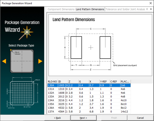
-
Tolerance and Solder Joint Analysis: Tab for entering the soldering
profiles of the package. Only for supported packages.
Figure 3. 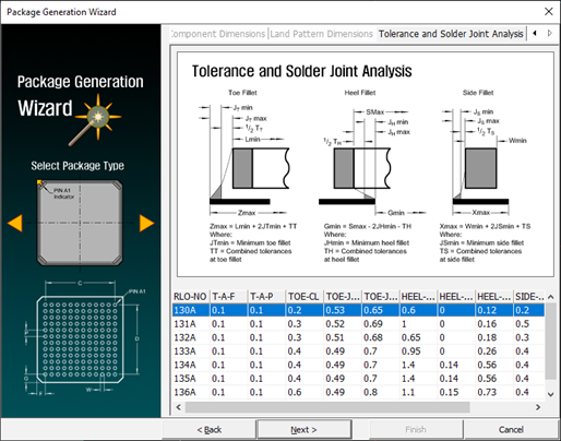
-
Land Pattern Dimensions: Tab for entering the pad size dimensions of
the package. Only for supported packages.
- Reference View: Show the reference views for dimensional input.
-
Dimension define method: Select the dimension define method.
- Basic: Define the dimensions with typical, minimum, and maximum values.
- Tolerance: Define the dimensions with typical value and minimum and maximum tolerances.
-
Add a new dimension setting.
- Type a. When the dimension defining method is basic.
Figure 4. 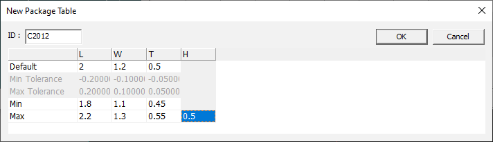
- ID: Unique ID of dimension setting.
- Default: Enter the typical dimension size.
- Min: Enter the minimum dimension size.
- Max: Enter the maximum dimension size.
- Tybe b. When the dimension defining method is tolerance.
Figure 5. 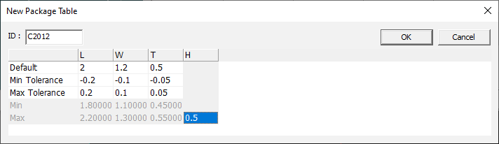
- ID: Unique ID of dimension setting.
- Default: Enter the typical dimension size.
- Min Tolerance: Enter the tolerance for minimum size.
- Max Tolerance: Enter the tolerance for maximum size.
- Type a. When the dimension defining method is basic.