Add and edit the configuration table for automatic logic symbol
generation.
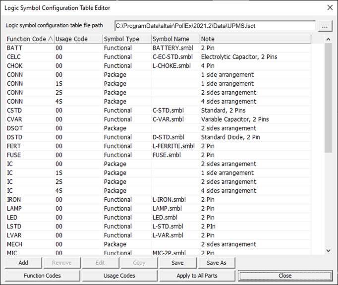
Figure 1.
Function Code: Display the function codes of each configuration tables. For a
function code, user can assign the product families to generate symbols
automatically. A product family can be assigned only one function code.
Usage Code: Display the usage codes of the function codes. Multiple usage codes
can be assigned to a function code for various logic symbol generations.
Symbol Type: Select the symbol type to be generated automatically. If the
Functional is selected, the logic symbols are generated referring the selected
functional logic symbol, and if the Package is selected, the logic symbols are
generated as a package shape.
Symbol Name: If the Symbol Type is selected, the Symbol Name must be defined.
Note: Describe note related the function code.
Add: Add a new configuration table.
Remove: Remove the selected configuration table.
If the Usage of selected configuration table is 00, it can’t be deleted
because 00 means the default and the default can’t be deleted.
Edit: Edit the selected configuration table. The menu windows are same with the
edit menus (Package, Functional) of the Add menu.