Add and edit the configuration table for automatic footprint generation.
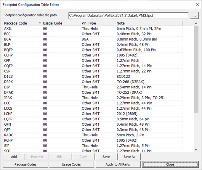
Figure 1.
-
Package Code: Display the package codes of each configuration tables.
For a package code, you can assign the packages to generate footprints
automatically.
-
Usage Code: Display the usage codes of the package codes.
Multiple usage codes can be assigned to a package code for various footprint
generations.
-
Pin Type: Select the pin type to be generated automatically.
BGA, Thru-Hole and Other SMT are available.
-
Note: Describe note related the package code.
-
Add: Add a new configuration table.