Case 1: Logic Symbol Type is Package
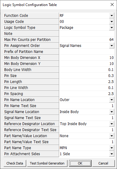
Figure 1.
- Function Code: Select the function code for generating the logic symbols.
- Usage Code: Select usage code.
- Logic Symbol Type: Select logic symbol type as Package.
- Note: Enter note related the function code and usage code.
- Max Pin Counts per Partition: Define the maximum pin counts for automatic logic symbol pin partitioning.
- Pin Assignment Order: Select the pin assignment ordering condition among pin names, pin numbers and signal names.
- Prefix of Partition Name: Define the prefix of automatically created partition names.
- Min Body Dimension X: Define the minimum body X size of symbol.
- Min Body Dimension Y: Define the minimum body Y size of symbol.
- Body Line Width: Define the line width of body figure.
- Pin Size: Define the pin size.
- Pin Length: Define the pin length.
- Pin Line Width: Define the line width of the pin figure.
- Pin Spacing: Define the pin spacing.
- Pin Name Location: Select the pin name location among Outer, On/Above/Below Pin Line and Inside of Body.
- Pin Name Text Size: Define the size of the pin name (text height).
- Signal Name Location: Select the pin signal name location among Outer, On/Above/Below Pin Line and Inside of Body.
- Signal Name Text Size: Define the size of pin signal name (text height).
- Reference Designator Location: Select the reference designator location among Top
- Outer/Inside Body and Center of Body.
- Reference Designator Text Size: Define the size of the reference designator. (text height)
- Part Name/Value Location: Select the part name or the value location among None, Bottom Outer/Inside Body and Center of Body.
- Part Name Type: Select the part name type to use among MPN, CPN and Value.
- Pin Attachment Sides: Define the pin attachment sides (1 or 2 or 4 sides).
- Check Data: Check if the input data are reasonable or not.
- Test Symbol Generation: Generate a test symbol using current data.