Assign Part Properties Automatically
Use the unified parts linked to assign part properties automatically.
-
In the Part library directory, click
 to navigate to explore the library path for the unified parts.
-
Click Synchronize to assign the part properties.
There are no check marks which are shown at the Package, Electrical, and Thermal columns. The check mark in the Package, Electrical, and Thermal columns means a component has Package/Electrical/Thermal information. After importing information from UPF, those icons are created depending on the existence of the corresponding information.
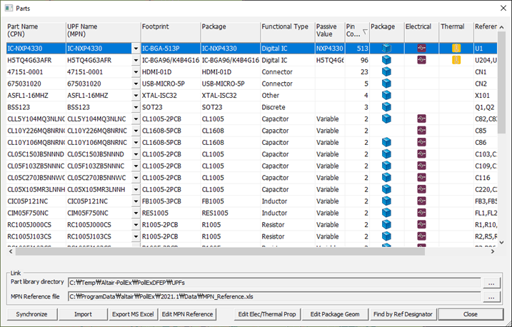
Figure 1.