Composite-Nets
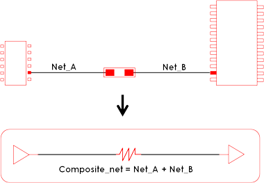
When two or more nets are serially connected through passive components such as resistor, electrical analysis must be made for the entire signal path encompassing the multiple nets connected with these passive components.
 |
 |
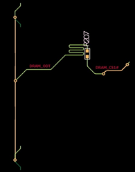
In Figure 1, two nets relate to the R207 resistor, without composite nets operation, these two nets might have open terminal for each then electrical simulation results for the nets wouldn’t be appropriate.
The Properties Composite Nets menu provides versatile ways to manipulate the Composite Nets generation and manage features with many options and operations illustrated below.
In Composite Component Area, you can select components to be used to generate composite net. Two nets connected with this component are modeled as composite nets.
After selecting composite component, clicking Generate Composite Nets, the list of composite nets will be displayed on composite net result display region.
Using the Add menu, you can manually specify the nets on which to composite.
You can remove or edit composite net result by clicking Remove or Edit.
By double-clicking one of composite net, the Edit dialog opens. You can change Net Type, Net Class, and Electrical Constraints.
By clicking the Composite Data field, you can review the composite net connection structure.
By clicking the Pin List field, you can review the component and pin number connected to this composite net.