Explore Tool Functions
Mount Equipment
Can add, delete, and modify the mounter information.
Edit Mount Data
Can edit the mount data directly.
- Search: Enters reference name to find and modify.
- Edit All Same Part Name: Used to modify the mounting coordinates and mounting angle of all parts with the same part name as the selected part.
- Edit Same Reference in All Board: This is used to modify the mounting coordinates and mounting angle of all parts with the same reference name. When C1 is selected, C1 of each 1st and 2nd boards arranged in sequence is applied.
- Edit: Coordinate correction button and angle adjustment button are applied only when it is selected. If you select a part and click the Edit button, the content of the part being edited will appear in the Edited List window at the bottom, and the status of the top list will be displayed as Editing.
- Coordinate: Modifies the coordinates.
- Uses the + and-buttons on the left to modify the left and right buttons on the X axis, and the up and down buttons on the Y axis. The data expressed in the list is the original data of the actual mounting data, and both the X and Y axes operate based on the original data of the mount.
- When the Coordinate value is set to 0.5 and the + button on the Y-axis is pressed, it is modified to 50.500 -> 51.000 in the List.
- Rotation: Adjusts the angle of parts. Press the corresponding radio button, and use the left, right, -and + buttons to rotate the selected part by the value entered.
- Apply: Click Apply after editing, the edited value of the edited list below will be reflected in the list above, the Status will be changed back to the original.
- Reset: Restores the original state again without reflecting the correction value of the mount data.
Compare Mount Data
Compares multiple mounting data or compare part coordinates and angles on mounting
data and PCB design.
- Search: Enters the reference name to find.
- Tolerance: Sets tolerance.
- Display Mode: Selects whether to view the read file as Actual Value or Difference Value.
- Load Comparison File: Loads the mounting data for verification and mount data for comparing.
- Compare with PCB: Can compare the part coordinates and angles from the mount data for verification and from PCB design.
Verification
Can review the matching result between pad and lead.
- Ref Name: Displays all parts as reference name.
- Part Name: Display all parts as part name.
- Layer: Displays part placed layer.
- X, Y: Displays X, Y coordinate of each part.
- Angle: Displays angle of each part.
- Result: Displays the detected error reason.
Board X/Y Cut
Check the PCB cutting surface. From the menu bar, click . The Board X/Y Cut dialog opens.
- Slice Plane: Select the X or Y axis of the cut plane.
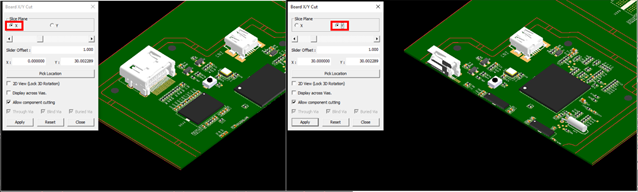
Figure 1. - Scroll: Move the selected cutting plane by moving the slider scroll.
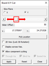
Figure 2. - Slider Offset: Slide bar moves by the Slider Offset value.
- X, Y: Indicate the X, Y coordinates of the cutting plane.
- Pick Location: Specify the cutting plane location by clicking the desired location.
- 2D View (Lock 3D Rotation): Display the cutting surface in 2D.
- Display across Vias: Select whether to display Vias in the cutting plane.
- Allow component cutting: Select whether to cut the component.
- Through Via, Blind Via, Buried Via: Select whether to display per via type.