Define Environment Settings
From the menu bar, click . The Mounting Emulator Environment dialog opens. The Mounting Emulator Environment dialog opens.
Global Parameters
- Mounter Type: Select a mounting equipment.
- BOM Environment
- BOM Setting File (*.EBI) Path: Sets the Excel BOM setting file (*.EBI) created from PollEx BOM.
- Define Part List Column Name: If does not use the Excel BOM configuration file (*.EBI) created by PollEx BOM, can set, and use the column information of Excel data.
- Mounting Library: Creates mounting data by referring to the Mounting Part
Code Table when the part code used in the mounter is different from the part
data used in the PCB data and BOM.
- Mounting Library File Path: Selects the part code used in the Mounter, and the Part Code Matching Table file used in the PCB and BOM.
- Default Property Selection
- Part and Reference Comment: Sets the property where the value for each part of PCB design is registered.
- Property Value Matching: Recognizes parts information that matches both the Property Value and Part Name on the PCB design from the Mounting Part Code Table.
- Define Column Name: Sets the column of Excel which is defined in
Mounter Library File Path.
- Part Code: Set the column name where the Part Code is described.
- Mounting Part Code: Sets the column name describing the Mounting Part Code.
- Property: Sets the column name where the property is described.
- Decimal Place: Set the default decimal place when generating mounting coordinate data. Select a value from 1 to 5.
- Tolerance
- Allowable Distance: When mounting parts based on mounting data, set tolerance values even if they do not exactly match the parts positions on the design.
- Correct Type: Sets whether to correct only the mounting angle or both the mounting coordinates and the angle when the Correct All button is pressed in the mounting verification result.
- Make Mount Data Change Log File: Saves log of modified records through Mounting Emulator.
Board Parameters
- Board Origin Location: Sets board origin.
- Set nearest sub board from board origin as block data: Sets the sub
board closest to the selected Board Origin as Block Data.
- Generate block data only: Exports only block data when outputting mount data.
- Set nearest sub board from board origin as block data: Sets the sub
board closest to the selected Board Origin as Block Data.
- Use Changed Board Origin: Allows you to use the origin set by the user without using the bottom left point of the entire area of the board.
Component Parameters
- PoP Component Definition: For parts with high component densities, such as
mobile phones and digital cameras, a package on package (PoP) design is
sometimes applied. Option to check if the position of pin 1 of the upper
part of the PoP is the same as the position of pin 1 of the lower part.
- Filter: Sets through the string filter to recognize the top part of
the POP from the mount data.
Figure 1. 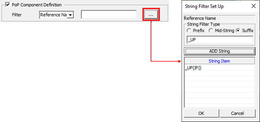
- In the above example, the part with the same reference name and the suffix _UP is recognized as the top material of the PoP. For example, if U100 parts and U100_UP parts exist in the mounting data, U100 parts are recognized as lower parts and U100_UP parts as upper parts.
- Filter: Sets through the string filter to recognize the top part of
the POP from the mount data.
- Except Component: Excludes components on the PCB design that are not the target components, such as Test Point, Screw, Fiducial Mark, and so on, when exporting mount data. Set it using the part DB file (*.txt) file.
- Allowable Component with the Rotated 180 Degrees: Sets the parts that allow
180 ˚ back-insertion, such as chip parts without polarity.
- Use UPF Option(Rotated 180 Degrees): Allows 180˚ back-insertion for parts with the option to allow 180˚ back-insertion in the UPMS mount data option.
- Define Component List Path: Allows 180˚ back-interpolation using the part group file.
- Export Component Angle as 0 or 90 Degrees: Exports 0 degrees in the horizontal direction and 90 degrees in the vertical direction for parts corresponding to the specified Component DB (*.txt) file.
Fiducial Parameters
- IC Fiducial Mark Definition: Sets location and shape of IC fiducial mark on
board.
- Component: When the IC fiducial mark is designed as a component on the PCB design, it can be recognized using a string filter.
- String Filter: Selects String Filter Type from prefix, mid-string,
suffix, and input the string for part recognition. The example below
means that the part name on the PCB design recognizes all parts
starting with IC_FID.
Figure 2. 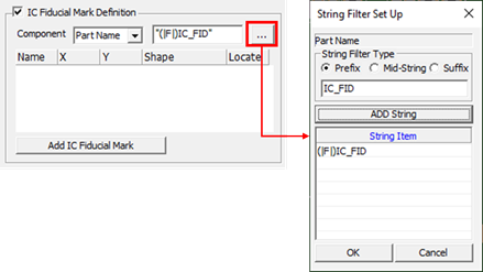
- Bad Mark Definition: Sets location and shape of bad mark on board.
- Component: When the bad mark is designed as a component on the PCB design, it can be recognized using a string filter.
- String Filter: Selects String Filter Type from prefix, mid-string,
suffix, and input the string for part recognition. The example below
means that the part name on the PCB design recognizes all parts
starting with MARK_BAD.
Figure 3. 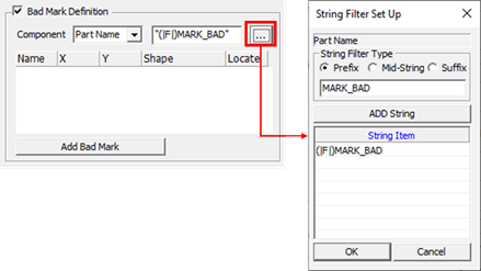
Display Parameters
- Display Sub Board: This is an option to set the 3D Package Display
status.
- All: Displays 3D Package shape for all sub boards.
- Sub Board: Displays 3D Package shape for one sub board.
- None: 3D Package shape is not displayed.
- Result Display Setting
- Result Confirm: Exports option to check whether the coordinates and
angles have been distorted. If the user does not check all the parts
that are distorted, correction of the mounting data cannot be
performed.
- Location Difference: Result Confirm function is applied to the part with the coordinate misalignment.
- Angle Difference: Result Confirm function is applied to the part with angle distortion.
- Display No Mounting Data: It is an option to display the failure caused by parts that are used in the design data but do not exist in the mounting data.
- Result Confirm: Exports option to check whether the coordinates and
angles have been distorted. If the user does not check all the parts
that are distorted, correction of the mounting data cannot be
performed.
- Display package Mark: Option to draw a mark on the 3D package surface.
- User defined mount data format setting: Sets item using the User Defined Export function in Export-Direct Generation Result.
User Defined Export Format Setting Dialog Parameters
- Board Size: Sets the information of board size.
- Title String: Set the string for title.
- Column Count: Set the number of columns.
- Table: Set exporting format for each column.
- Origin Location: Sets exporting format for board origin.
- Title String: Set the string for title.
- Column Count: Set the number of columns.
- Table: Set exporting format for each column.
- Origin Offset: Sets offset information of origin.
- Title String: Set the string for title.
- Column Count: Set the number of columns.
- Table: Set exporting format for each column.
- Fiducial Mark: Sets exporting format for fiducial mark.
- Title String: Set the string for title.
- Column Count: Set the number of columns.
- Table: Set exporting format for each column.
- Fiducial Light: Sets exporting information of fiducial light.
- Title String: Set the string for title.
- Column Count: Set the number of columns.
- Table: Set exporting format for each column.
- Placement Coordinate: Sets exporting format for part placed coordinates.
- Title String: Set the string for title.
- Column Count: Set the number of columns.
- Table: Set exporting format for each column.
- Array Count: Sets exporting format for array board information of sub
board.
- Title String: Set the string for title.
- Column Count: Set the number of columns.
- Table: Set exporting format for each column.
- Array Coordinate: Sets exporting format for each sub board’s origin.
- Title String: Set the string for title.
- Column Count: Set the number of columns.
- Table: Set exporting format for each column.