Block JIG Rule Setup
The Block JIG Setting Rule dialog contains the followings
options:
- Base Line: For the bottom surface where the SMD process is completed, the
engraved machining area should be designed to avoid interference with parts.
Set the standard for creating the base line which is the engraved machining
area.
Figure 1. 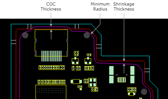
- Min Radius: Set the minimum radius value for the base line. The larger the setting value, the smoother the curvature of generated base line and the shorter the manufacturing time of the JIG. If the PCB shape is complicated, the minimum radius value should be set smaller.
- COC Thickness: The base line should be formed avoiding the component area to prevent interference with the component. The component COC (Component Outline) on the PCB design data should be expanded by the set value to prevent interference with the component.
- Shrinkage Thickness: Based on the outline of the unit PCB, a base line is formed based on the reduced area by the entered value. If the base line is bigger than the PCB area, the vacuum adsorption force and supporting stability will be deteriorated.
- Supporter: Set the rules for creating supports in empty space where
components are not placed inside the base line area.
Figure 2. 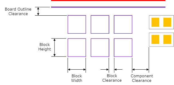
- Block Width: Set the width value.
- Block Height: Set the height value.
- Block Clearance: Set the clearance value between supports.
- Board Clearance: Set the clearance between support and base line.
- Component Clearance: Set the clearance between support and component.
- Boundary Line: Set the rules for creating the boundary line.
Figure 3. 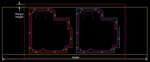
- Width: Enter the horizontal size of the boundary line.
- Margin Height: Enter the margin between the boundary line (highlighted in yellow) and the panel PCB outline (highlighted in magenta) of the upper or bottom side.
- Shared Block: Set the rules for creating the shared block.
Figure 4. 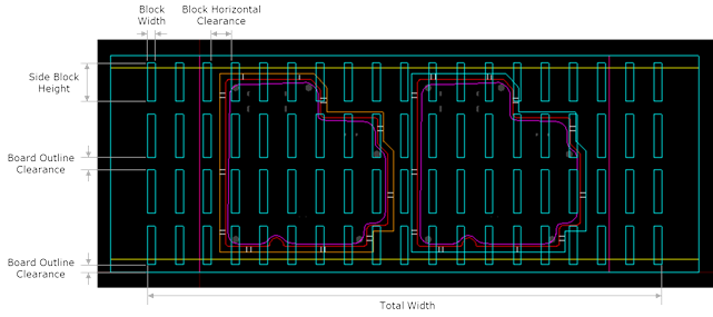
- Total Width: Enter the total width value of the support.
- Block Width: Enter the width value of the support block.
- Side Block Height: Enter the height value for the top and bottom edges.
- Board Outline Clearance: Enter the clearance value between the board outline and the supports of the top and bottom edges.
- Block Horizontal Clearance: Enter the horizontal clearance value between supports.
- Block Vertical Clearance: Enter the vertical clearance value between supports.
- Bottom: Set the value for making the block JIG bottom.
Figure 5. 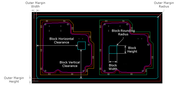
- Outer Margin Width: Enter the margin width value to create the outer line of the block JIG bottom.
- Outer Margin Height: Enter the margin height value to create the outer line of the block JIG bottom.
- Outer Margin Radius: Enter the radius value of the outer line of the block JIG bottom.
- Block Width: Enter the width value of the bottom alignment pin support.
- Block Height: Enter the height value of the bottom alignment pin support.
- Block Rounding Radius: Enter the radius value for the corners of the bottom alignment pin support area.
- Block Horizontal Clearance: Enter the horizontal clearance value of the bottom alignment pin support.
- Block Vertical Clearance: Enter the vertical clearance value of the bottom alignment pin support.