PCB Outline and Bridge Recognition
The Base Line section contains the following options:
- Select Gerber Layer: Select a Gerber Layer to select outline and bridge
object of panel board. The selected Gerber layer displays on the screen.
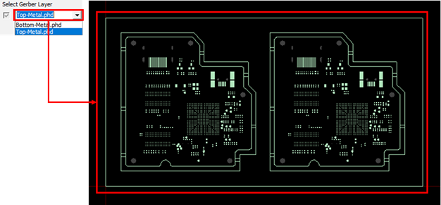
Figure 1. - Select Top Component: Select the CAD data layer that corresponds to the top
surface during the screen print process. The components placed on the bottom
surface are engraved in the base line area to avoid interference with the
Block JIG. Therefore, if the top side is selected, the component area placed
on the bottom is referred to when creating the base line, and vice
versa.
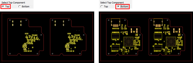
Figure 2. - Recognize Bridge: When the unit PCB outline and the panel PCB outline are
parallel, a pair line at the right angle is regarded as a bridge region. The
bridge area should be recognized to distinguish the unit PCB outline from
the panel PCB outline.
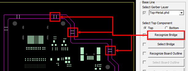
Figure 3. - Select Bridge: When the bridge is not recognized automatically when you click Recognize Bridge, the bridge can be manually set by selecting two lines.
- Recognize Board Outline: This menu distinguishes and recognizes each closed
outline considering the connection status of the outline. The closed
outlines display in different colors when you click Recognize
Board Outline.
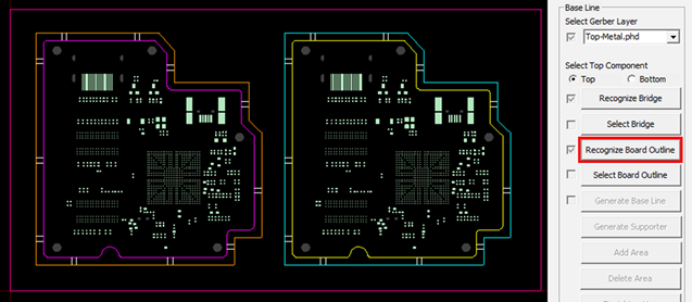
Figure 4. - Select Board Outline: Board outline is created based on the unit PCB outline
when creating the base line. Select the outlines corresponding to the unit
PCB among the outlines separated by clicking Recognize Board
Outline.
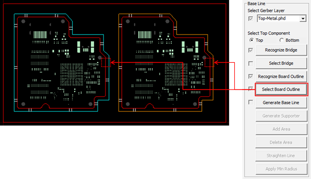
Figure 5. - Generate Base Line: When you click Generate Base
Line, the base line is generated with purple.
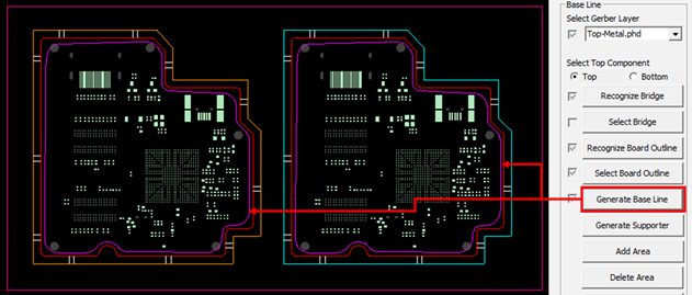
Figure 6. - Generate Supporter: When you click Generate
Supporter, the support is generated in the area where the
components are not placed inside the base line.
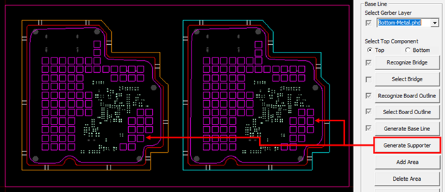
Figure 7. - Add Area: Click Add Area to add the base line area, and then click
Done.
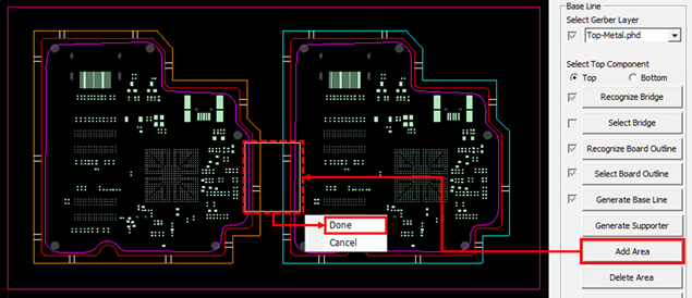
Figure 8.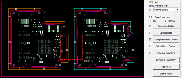
Figure 9. - Delete Area: If you want to delete the base line area, click
Delete Area to select the area, and then click
Done.
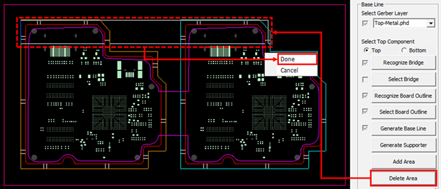
Figure 10.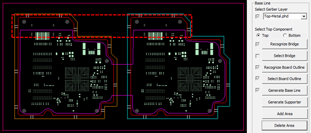
Figure 11. - Straighten Line: To convert the created base line into a straight line,
click Straighten Line, click two points to be
straightened, and then click Done.
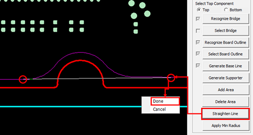
Figure 12.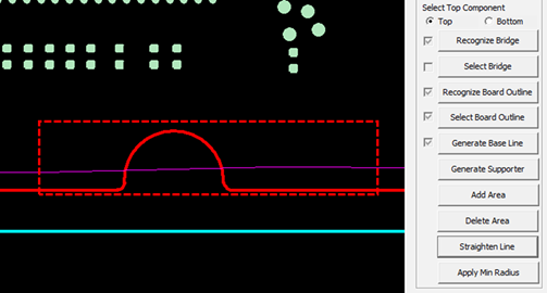
Figure 13. - Apply Min Radius: Rounded corners are processed by reflecting the minimum
radius value on the edited base line through the Add Area, Delete Area, and
Straighten Line functions.
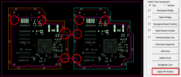
Figure 14.