
Spray Quench Zone
Inspire Extrude support two types of spray cooling zones - rectangular and circular.
Rectangular Spray Zone
Each side of a rectangular quench zone can have a combination of line set and nozzle set, which can be enabled/disabled for a specific run. By default, top side is enabled. Each line set is made of set of lines, by default 5 lines and each line has a set of nozzles, by default 4 nozzles.
-
From the Quenching ribbon, click the
Quench tool.

The secondary toolbar with quench zone types is displayed.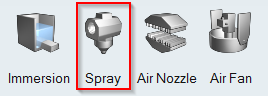
-
Click the Spray icon.
Adjust the zone position over the profile using the move tool
 in the
microdialog to move the box in X,Y, Z directions.Clicking the
in the
microdialog to move the box in X,Y, Z directions.Clicking the


 buttons in
the microdialog enables/disables the sides in the top, bottom, right or left of
the zone respectively. This feature is disabled for Circular zone type, since it
is not applicable.A rectangular spray zone will be created. Micro dialogs to edit the box dimensions will be populated along the width,length and height of the box. Another micro dialog with spray zone parameters will be populated.
buttons in
the microdialog enables/disables the sides in the top, bottom, right or left of
the zone respectively. This feature is disabled for Circular zone type, since it
is not applicable.A rectangular spray zone will be created. Micro dialogs to edit the box dimensions will be populated along the width,length and height of the box. Another micro dialog with spray zone parameters will be populated.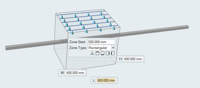
-
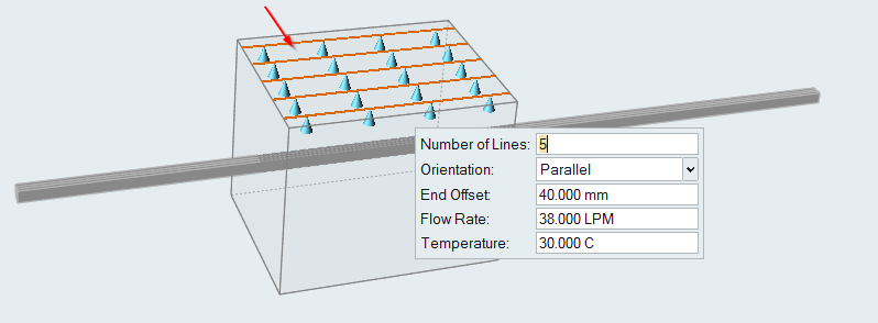
Change the parameters of the line set by clicking the line set.
In the microdialog, edit the parameters and press Enter.
The line set will be recreated with the new values.The flow rate specified is for the entire side, and is equally divided to each line. Lines are positioned at equal distances on the side, with the specified end offset (both ends). Temperature of the coolant is also specified in this dialog. Line orientation can be parallel or perpendicular. If it is parallel, then it will along the Z axis, otherwise it is perpendicular to the Z axis.
-
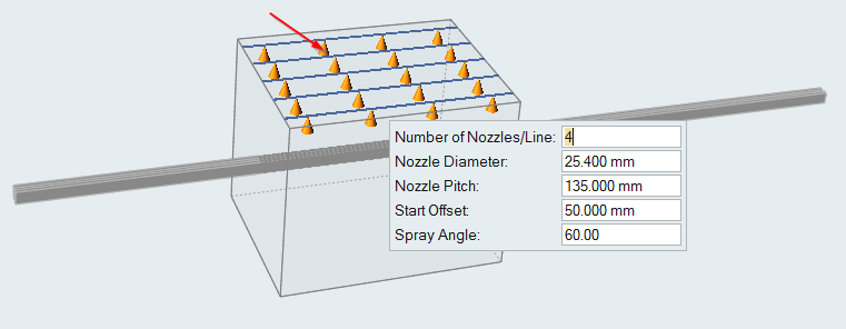
Change the parameters of the nozzle set by clicking the nozzle set.
In the microdialog, edit the parameters and press Enter.
The nozzles will be recreated with the new values.Nozzle Pitch is the distance between two nozzles. The position of the first nozzle is specified from the starting edge of the zone using the Start Offset value.
- Repeat the above steps to create line sets and nozzle sets for the other surfaces of the zone.
- Right-click to exit the spray zone edit context.
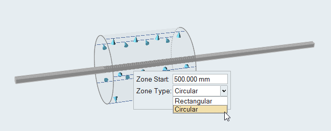
Circular Spray Zone
To create a circular spray zone, select Circular type from the drop down. A circular quench zone has a set of lines placed at equal intervals on the circumference of the zone, and each line has a set of nozzles.
-
From the Quenching ribbon, click the
Quench tool.
The secondary toolbar with quench zone types is displayed.
-
Click the Spray icon.
A rectangular spray zone will be created.
-
Click on the edge of the
box. The spray zone context is activated. From the spray zone dialog, select
Circular from the drop down.
-
Edit the Zone Start field in the microdialog. Enter the
dimensions of your quench zone in the Length and
Diameter microdialogs. Clicking one of the edges in
the zone populates them.
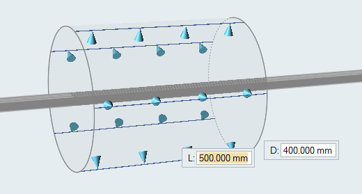 On Enter, the zone will be recreated based on the entered dimensions. Lines and nozzles are created based on the dimensions of the zones.
 - Optional:
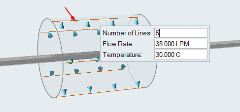
Change the parameters of the line set by clicking the line set. In the
microdialog, edit the parameters and press Enter.
The line set will be recreated with the new values. Lines are positioned at equal intervals on the circumference of the zone. The flow rate specified is equally divided among all of the lines.
- Optional:
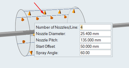
Change the parameters of the nozzle set by clicking the nozzle set. In the
microdialog, edit the parameters and press Enter.
The nozzles will be recreated with the new values.
- Press Esc to exit the spray quench context.