
Tutorial: Getting Started with the Binder Sinter Ribbon
Learn how to prepare, orient, analyze, and export a compensated part for 3D printing.
Create the Model
- Select MMKS as the unit system.
- Open the Sketch ribbon.
- Select the New Sketch tool.
- Select the Z plane as the sketch plane.
-
Select the Circle by Center and Point tool.

Tip: To find and open a tool, press Ctrl+F. For more information, see Find and Search for Tools. -
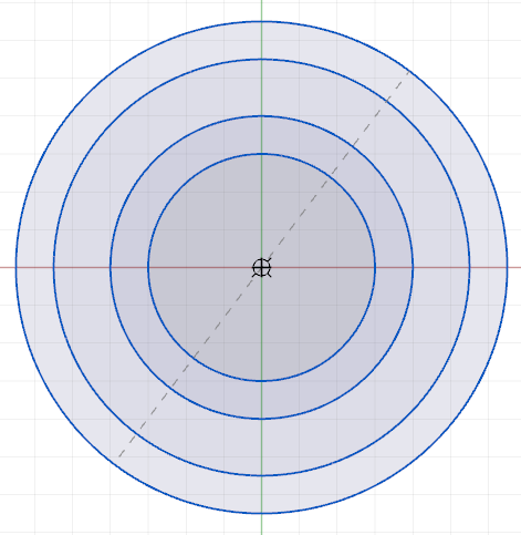
Create four concentric circles around the point of origin, with diameters of 60
mm, 80 mm, 110mm, and 130mm, respectively.
-
Select the Regular Polygon tool.

In the guidebar, select 3 Sides. Create an equilateral triangle 12 mm from center to angle, centered on the intersection of the outermost circle and the X axis.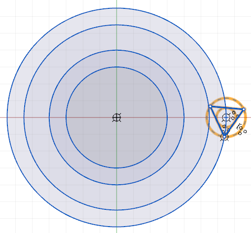
-
Select the Trim tool.

Remove the segments of the triangle inside the outermost circle. Remove the sketch curves as shown below.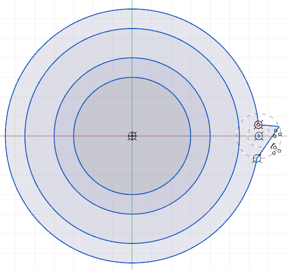
-
Select the Circular Pattern tool.

Select the two remaining sketch curves of the triangle as the entities to pattern. Select the point of origin as the Center. Select Pattern by Equal Spacing. In the Angle field, enter 360 degrees. In the Copies field, enter 18. Click the Apply button.
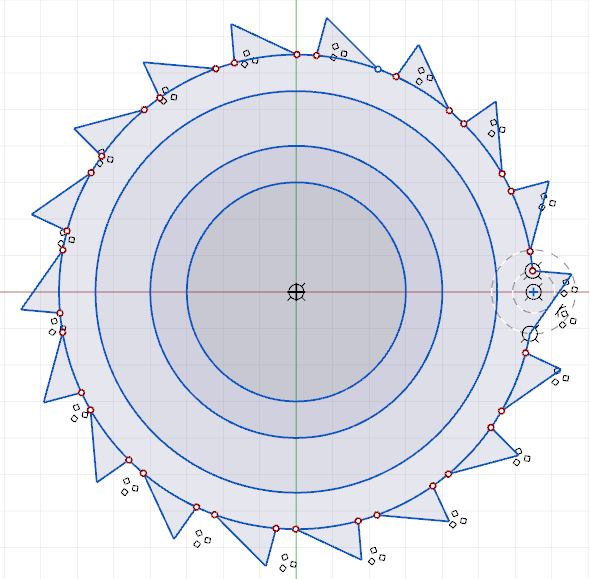
-
Select the Trim tool.
Trim the arcs as shown.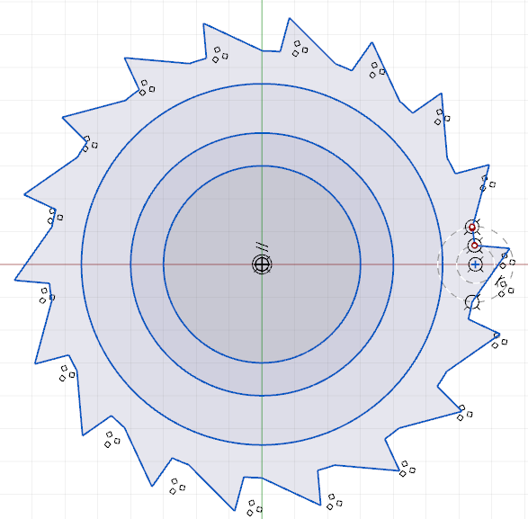
- Open the Geometry ribbon.
-
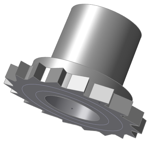
Select the Extrude tool.

Select the surface between the smallest circle and the next larger one. Extrude the surface to 100 mm. Click the Apply button.
-
In the Extrude window, under Result, select
Combine.

Select the next surface. Extrude it to 30 mm. Click the Apply button.
-
Select the toothed surface. Extrude it to 15 mm. Click the
Apply
button.
-
In the Extrude window, under Result, select
Subtract.

Select the innermost surface on the bottom of the model. Extrude it to 25 mm. Click the Apply button.
-
Right-click and mouse through the check mark to exit, or double-right-click.
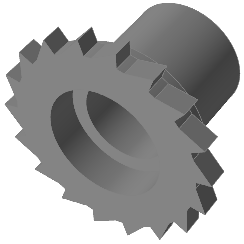
Select the Part to Print
- Open the Print3D ribbon.
-
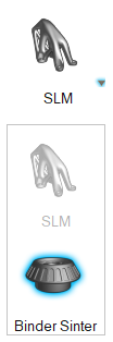
Select Binder Sinter from the Print
Mode menu.
-
Select the Print Part icon on the
Print3D tab.

- In the moideling window, select the part you just created to designate it as the part to be printed.
-
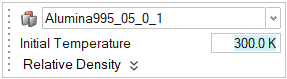
Select the Alumina995_05_0_1 material in the drop-down
menu to assign a material to the print part. Leave the Initial Temperature and
Relative Density at their devault settings.
Configure the Oven
-
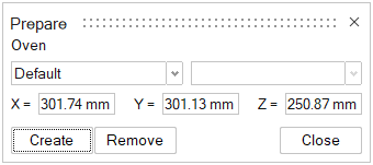
Click the Oven icon to configure the oven.

-
Choose the default oven.
-
Click Create. The part appears in the configured
oven.
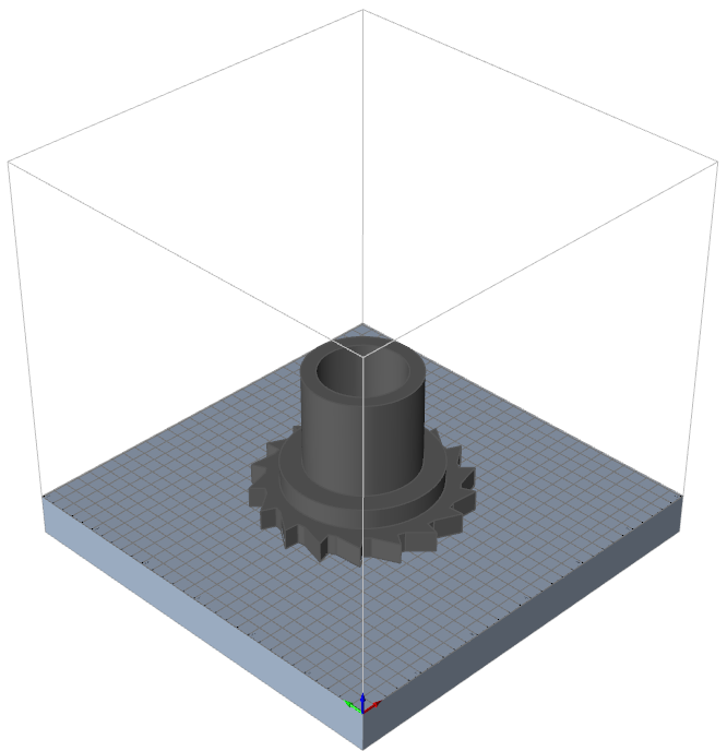
Orient the Model
-
Click the Orientation icon.

-
Click the Surface icon.

Then select the top surface of the model.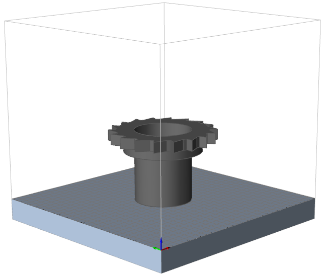
-
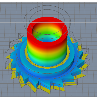
Test the orientation. Click the Sag Preview icon.

The sag preview shows high deformation of the top of the model.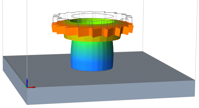
-
Reorient the model for better results. Click the Surface
icon.
Then select the top surface of the model. The model reorients with the toothed surface in contact with the oven base. -
Click the Sag Preview icon.
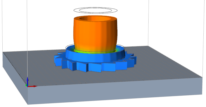 The sag preview still shows some areas of high deformation.
Support the Model
-
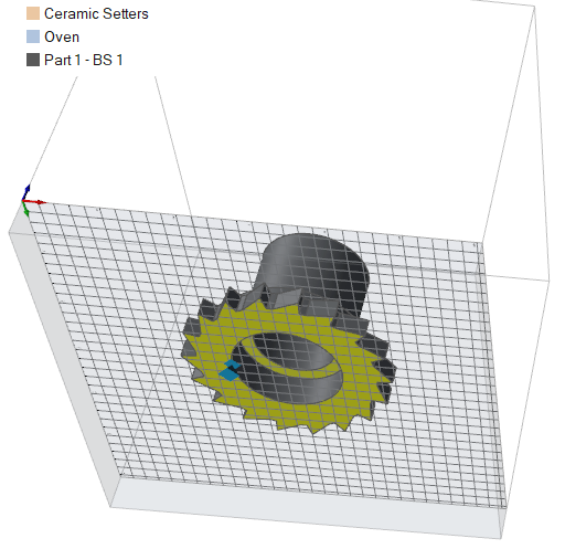
Click the Setter tool in the Print3D ribbon.

- Tilt the model so that you can see the bottom surfaces. Select the inner circular surface. Inspire will create a virtual setter to support the model.
-
Right-click and mouse through the check mark to exit, or double-right-click.
Note: The setter will not be visible in the modeling window, but you will see Ceramic Setters appear in the legend at the top left.
Run a Compensation Analysis
-
Click the
 button on the Analyze
icon.
button on the Analyze
icon.

-
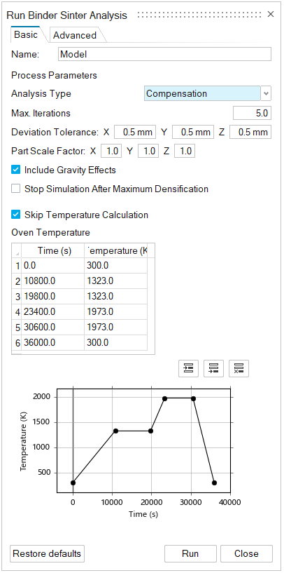
Set your process parameters. Select Compensation for the
Analysis type. Leave the other controls in their
default settings.
-
Click Run to run the analysis. A green flag is displayed
over the Analyze icon when the analysis is complete.
 Note: The analysis may take some time to run, depending on your computer's processing power.
Review the Analysis Results
-
When the run has completed successfully, click the Show Analysis
Results tool on the Analyze icon to open
the Analysis Explorer.

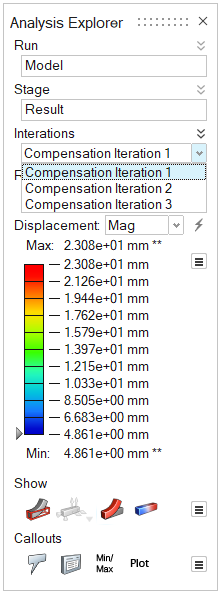
-
Iteration 1 of the compensation analysis is shown in the modeling window. The
designed part’s outline shows the discrepancy between the designed part and the
finished product.
-
Review the results for Compensation Iteration 2 and 3. Note how the results for
each iteration is closer to the designed part.
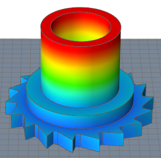
- Try animating the results to see how the compensated part deforms into the designed shape.
- Right-click and mouse through the check mark to exit, or double-right-click.
Export the Model and Supports
-
Click the Green Part icon.

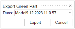
- Click Export.
- Navigate to the file path where you want the exported Green Part file to be saved.
-
in the Explorer window, name the file as desired and click
Save.
The compensated part file can be found in the designated location.Note: If you use a virtual setter in your simulation, as we did in this exercise, remember to use a ceramic setter in the sintering process when fabricating your part.