Tutorial: Perform a Print3D Simulation
Learn how to prepare, simulate, and export an aerodynamic bracket design for 3D printing.
Designate the Part in the Model Geometry
- Press F7 to open the Demo Browser.
- Double-click the aero_bracket.stmod file in the Print3D folder to load it in the modeling window.
- Select MMKS as the unit system.
-
Select the Print Part icon on the
Print3D tab.

Tip: To find and open a tool, press Ctrl+F. For more information, see Find and Search for Tools. -
Select the part geometry to designate it as the part to print.
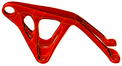
- Verify that the part material is set to Aluminum AlSi 10Mg.
- Right-click and mouse through the check mark to exit, or double-right-click.
Configure the Printer Bed
Create the printer bed and orient the part in the bed.
-
Select the Printer icon.

-
Keep the default parameters for the printer bed, then click the
Create button.
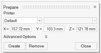
The printer bed is automatically generated for the part.
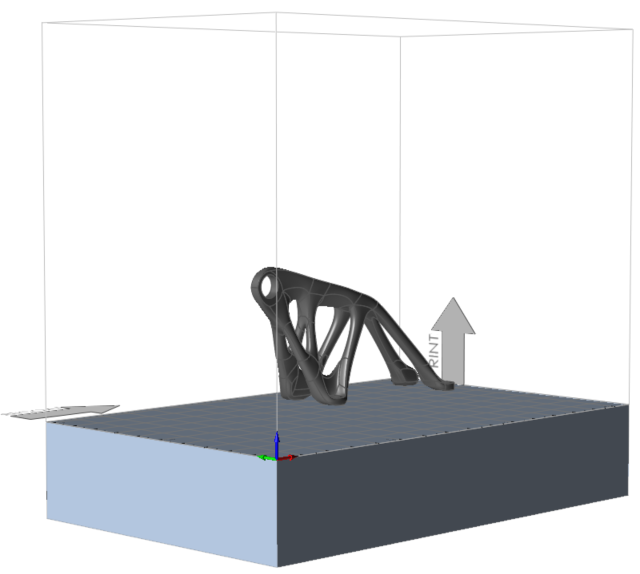
- Right-click and mouse through the check mark to exit, or double-right-click.
Orient the Part
You have multiple options to orient your part on the printer bed. The best option depends on the support and post-processing requirements for the part. Generally, the best orientation occurs with the fewest number of undercuts and supports.
-
Click the Orientation icon.
 The yellow highlighted surfaces show the possible areas to accommodate the support structure.
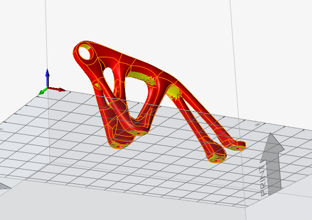
-
Click the Surface icon from the secondary ribbon

-
Select the surface shown below to orient it parallel to the printing bed.
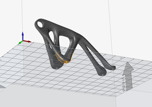
- The microdialog that appears lets you define options such as the distance between the part and the printer bed and whether you want to retain undercuts. Keep the default values and exit the tool.
Create Supports for the Part
-
Click the Create Supports tool on the Support
icon.
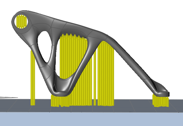
 Inspire auto-generates a support preview, which can be configured according to design needs. This automatically generated support cannot be printed as it appears.
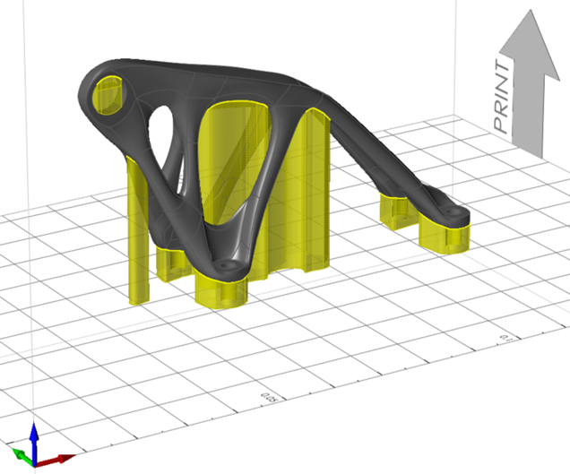
-
Hold the Ctrl key and select all of the supports to edit
them.
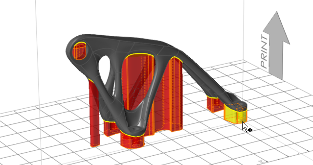
-
Select the Rod Supports
 icon, expand the Pattern section and select
Circle-shape section for the Shape.
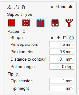
- Enter 1.5 mm for the Pin separation to define the spacing of the supports.
-
Click Generate on the microdialog to generate the
supports, and exit the tool.
The generated supports should look something like this:
Slice and Preview the Model
-
Click the Slice icon.

-
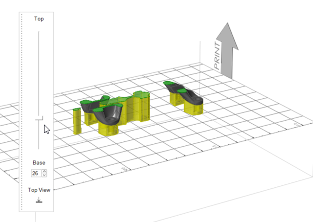
Drag the slider from the Base toward the Top to review the progression of the
printing layers. The gradual changes that you see in the geometry from layer to
layer are key for successful additive manufacturing.
-
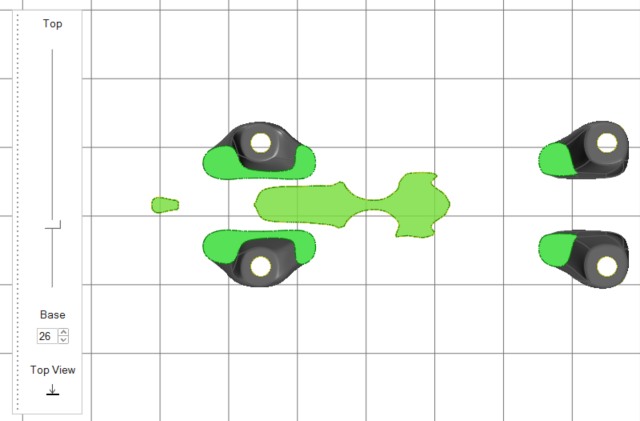
Click Top View
 to observe the part from above, as if looking down
at the printing bed.
- Right-click and mouse through the check mark to exit, or double-right-click.
Run an Additive Manufacturing Analysis
-
Click the play
 button on the Analyze
icon.

-
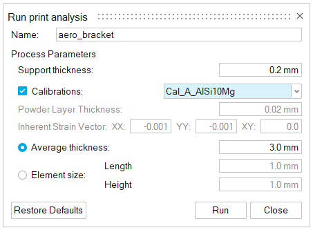
Define the parameters for the analysis as follows:
-
Click the Run button to run the analysis.
A green flag is displayed over the Analyze icon when the analysis is complete.

Review the Analysis Results
-
Click the play button
 on the Analyze icon.

-
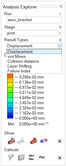
Select and review the result types in the Analysis
Explorer.
-
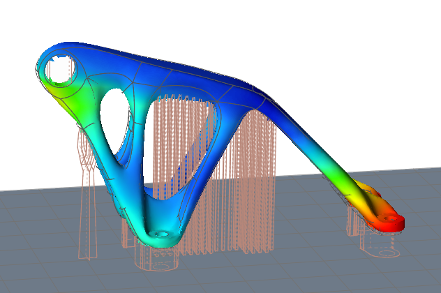
Select Displacement and review the results.
The displacement result type shows how much your model will displace or deflect during the 3D printing process. The areas of the model that are the darkest red will have the most displacement.
-
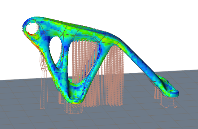
Select von Mises and review the results.
The von Mises stress results can be used to predict the part performance and durability. The areas shown in orange and red have exceeded the peak stress.
- To observe the springback effect on the model, select Springback from the Stagesmenu. Play the animation of the springback results.