
Tutorial: Getting Started with Print3D
Tutorial Level: Beginner Learn how to prepare, orient, slice, export, and analyze a part for 3D printing.
Open the Model
- From the menu bar, select .
-
Browse to your working directory, select
First_Test_Print.x_b, and click
Open.
The model opens in the modeling window.
- Select MMKS as the unit system.
-
Select the Designated Supports parts and delete them. (We will be creating new
supports later.) You can select and delete them individually, or Control + click
each of them to select them all, and delete them all at once.
Select the Part to Print
-
Select the Print Part icon on the
Print3D tab.

Tip: To find and open a tool, press Ctrl+F. For more information, see Find and Search for Tools. -
Select the PolyNURBS Block 1 part in the modeling window
to designate it as the part to be printed.
Note: You may get an error message that the currently assigned material does not exist in the database of materials. Inspire Print3D does not share the same material database as the core Inspire module, so you will need to reassign a material in the next step.
-
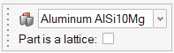
Select the AluminumAISi10Mg material in the drop-down
menu to assign a material to the print part.
Configure the Printer
-
Click the Printer icon to configure the printing bed.

-
Choose the EOS_M_290 printer.
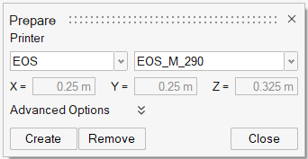
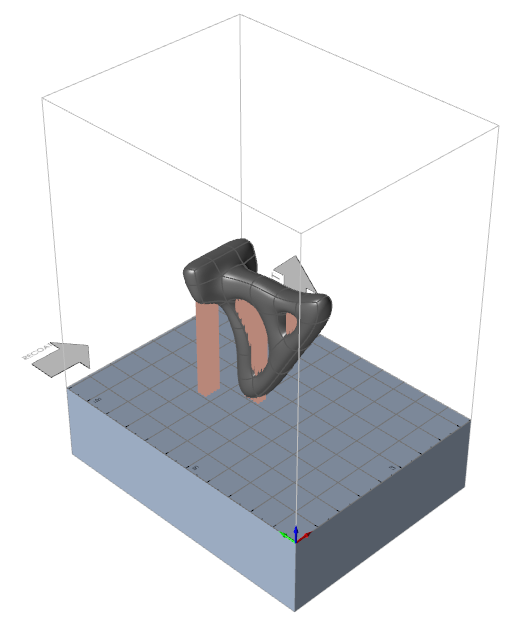
- Click Create. The part appears in the configured 3D printing bed.
-
Scroll to zoom in on the part.
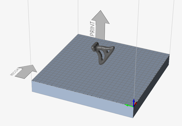
Orient the Model
-
Click the Orientation icon.

-
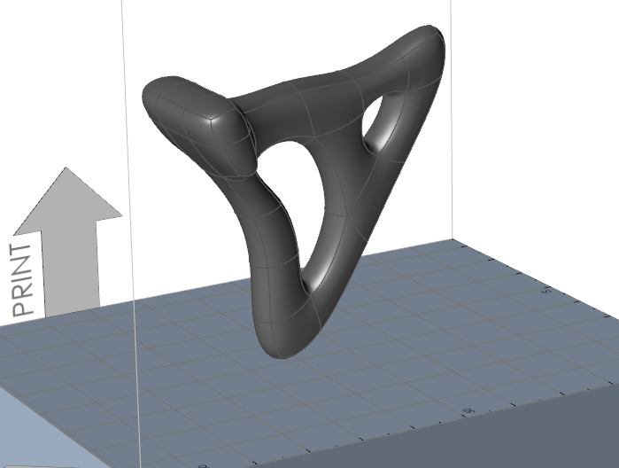
Observe the orientation tools. You have the option to minimize or maximize the
height of the print, or to orient a surface of the part parallel to the print
bed. You can also use the heat maps to minimize print time, needed supports, or
potential deformation. The part is already in an optimized orientation; leave
the part in its default orientation.
This orientation will maximize the build height to protect the part from cooling deformations.
Support the Model
-
Click the Create Supports tool on the Support
icon.
 Inspire auto-generates a support preview, which can be configured according to design needs. This automatically generated support cannot be printed as it appears.
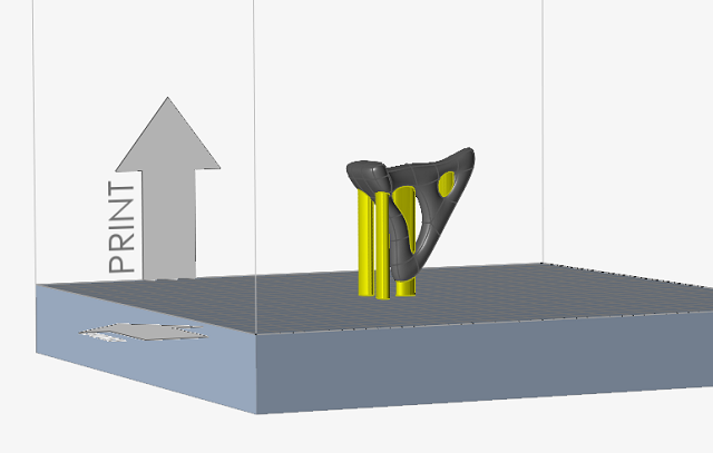
-
Hold the Ctrl key and select the supports shown below to
edit them. The selected supports turn red.
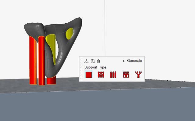
-
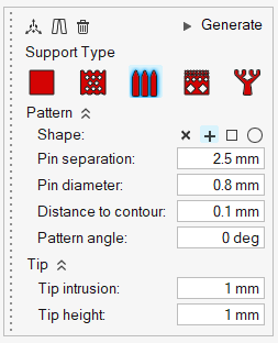
Select the Rod Supports
 icon, expand the Pattern section and change the Pin
Separation to 2.5 mm.
icon, expand the Pattern section and change the Pin
Separation to 2.5 mm.
-
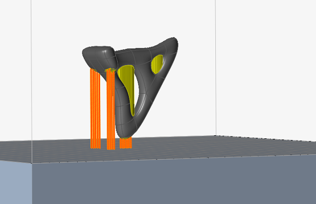
Click Generate on the microdialog to generate the
supports.
The selected support previews are converted to rod (pin) supports.
-
Now select the two supports in the interior holes and click the
Delete icon on the microdialog.
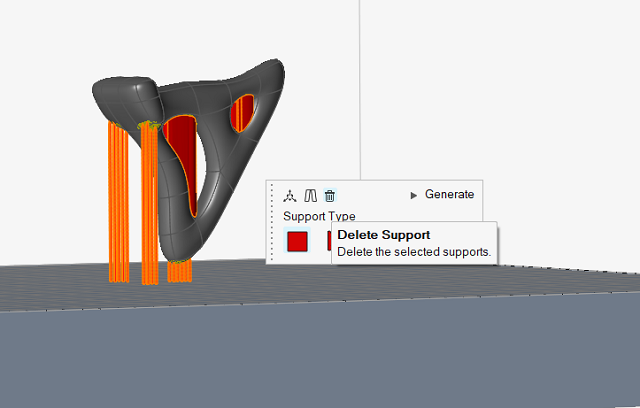 Note: Normally we would reposition the supports in the interior holes, but for this first tutorial we will simply delete and run the analysis without them.
 -
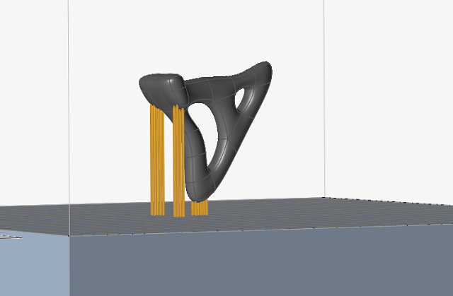
Right-click and mouse through the check mark to exit, or double-right-click.
Your model should look similar to the image below.
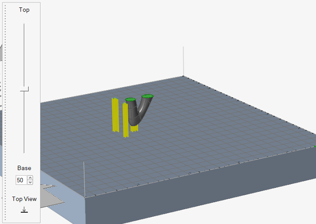
Slice the Model
-
Click the Slice icon.

-
Drag the slider from the Base toward the Top to review the the progression of
the printing layers. Gradual changes in the geometry from layer to layer are
needed for successful additive layer manufacturing.
-
Click Top View
 to observe the part from above, as if looking down
at the printing bed.
to observe the part from above, as if looking down
at the printing bed.
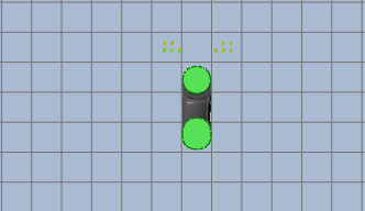
- Right-click and mouse through the check mark to exit, or double-right-click.
Run an Additive Manufacturing Analysis
-
Click the
 button on the Analyze
icon.
button on the Analyze
icon.

-
Set your process parameters. Enable Calibrations and
select Cal_A_AlSi10Mg from the dropdown menu.
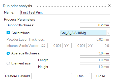
-
Click Run to run the analysis. A green flag is displayed
over the Analyze icon when the analysis is complete.
 Note: If you don't wait to wait for the run to complete before proceeding to the next step, you can load the First_Test_Print_Run.stmod file in the Print3D folder from the Demo Browser (F7).
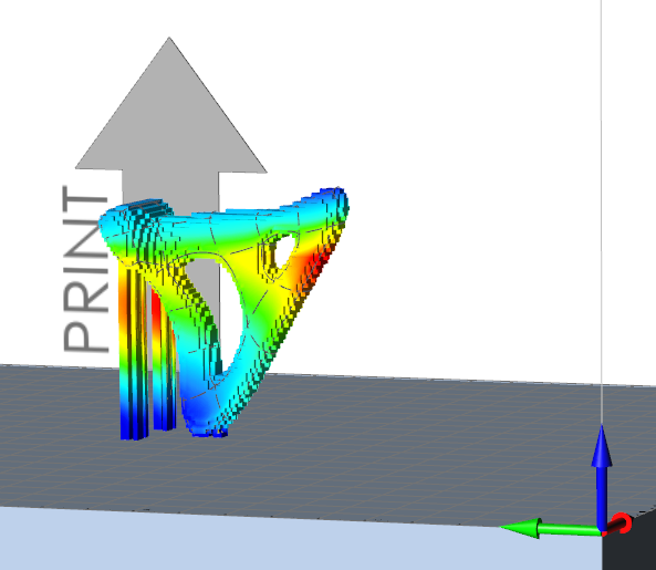
Review the Analysis Results
-
When the run has completed successfully, click the Show Analysis
Results tool on the Analyze icon to open
the Analysis Explorer.

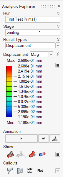
-
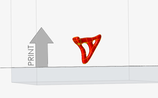
The displacement result type is displayed in the modeling window. The area of
greatest displacement is shown in red.
- Review the results for Displacement, von Mises stress, Collision Distance, Layer Shifting, and Failure Index.
- Try animating the results to see how the printed material changes during the printing simulation.
- Right-click and mouse through the check mark to exit, or double-right-click.
Export the Model and Supports
-
Click the Export icon.

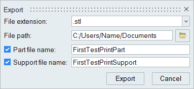
- Navigate to the File path where you want the exported files to be saved.
- Verify that both the Part and Support check boxes are enabled and name the files as desired.
- Click Export. The part and support files are generated separately and can be found in the File path location.