
Tutorial: Embedded Solids
Tutorial Level: Intermediate Learn how to use the Embedded Solids feature to simplify the process of making geometry modifications and running multiple design iterations.
Import CAD Model
- From the menu bar, select .
-
Browse to your working directory, select
MovableSolid_Tutorial.x_b, and click
Open.
The model opens in the modeling window.
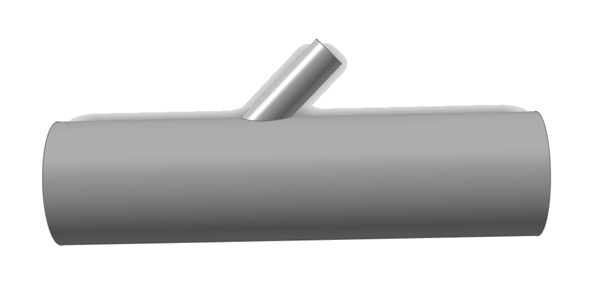
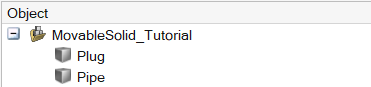
The model is comprised of the following parts:- Pipe
- Plug
-
You can view these parts in the Object Browser:
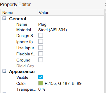
- In the modeling window, select the Plug.
-
In the Property Editor, set the color to Olive.
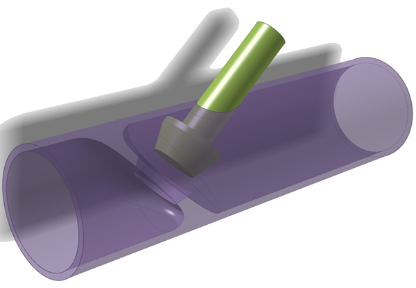
- In the modeling window, select the Pipe.
-
In the Property Editor, set the color to Purple and the
Transparency to 50.
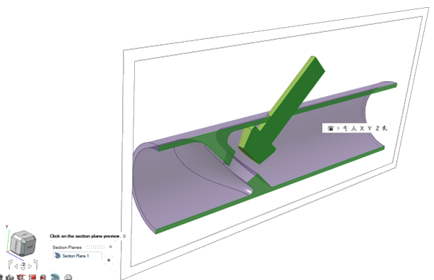
Create Section Cut
Create a section cut in the Z direction.
-
In the bottom-left of the modeling window, select Section
Cuts
 .
.
- Click the grey section cut pane.
- In the microdialog, select Z.
-
Right-click and mouse through the check mark to exit, or double-right
click.
The section cut is applied.
Assign Bounding Solid
Assign the bounding solid. Bounding solids provide the bounding faces for fluid domain extraction.
-
On the Fluids ribbon, select the Bounding
Solid tool.

Tip: To find and open a tool, press Ctrl+F. For more information, see Find and Search for Tools. -
In the modeling window, select the Pipe.
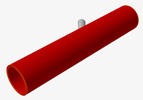
The part turns red and the material microdialog opens. - Right-click and mouse through the check mark to exit, or double-right-click.
Assign Embedded Solid
Assign the embedded solid. Embedded solids are considered as obstacles to the fluid flow. They are not used for fluid domain extraction, so they can be repositioned without needing to regenerate the fluid domain.
-
On the Fluids ribbon, select the Embedded
Solid tool.

-
In the modeling window, select the Plug.
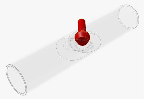
The part turns red and the material microdialog opens. - Right-click and mouse through the check mark to exit, or double-right-click.
Create Fluid Domain
-
On the Fluids ribbon, select the Create Fluid
Domain tool.

The bounding solid is automatically highlighted in red and the material microdialog opens.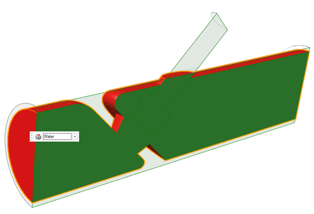
-
Ensure the material is set to Water.
The fluid domain is highlighted in blue.
- Right-click and mouse through the check mark to exit, or double-right-click.
Designate Inlet and Outlet Boundaries
-
On the Fluids ribbon, select the
Inlet tool.

-
Select the face as highlighted below.
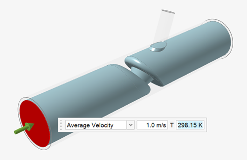
- Right-click and mouse through the check mark to exit, or double-right-click.
-
On the Fluids ribbon, select the
Outlet tool.

-
Select the face as highlighted below.
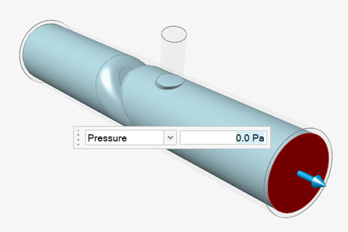
- Right-click and mouse through the check mark to exit, or double-right-click.
Run Analysis
Complete analysis 1 for the Embedded solids tutorial.
-
Click Run.
The Convergence Plot and Run Status windows open.
- In the plot window, click Show Convergence Table to review the inlet and outlet data.
- Once the analysis is complete, close the plot and status windows.
-
On the Fluids ribbon, select the Import
Runs tool from the Analyze tool group.

The Analysis Explorer opens. -
View the Engineering Quantities table.
-
In the Convergence Plot window, click
 next to Engineering
Quantities.
The engineering quantities table appears.
next to Engineering
Quantities.
The engineering quantities table appears.
-
In the Convergence Plot window, click
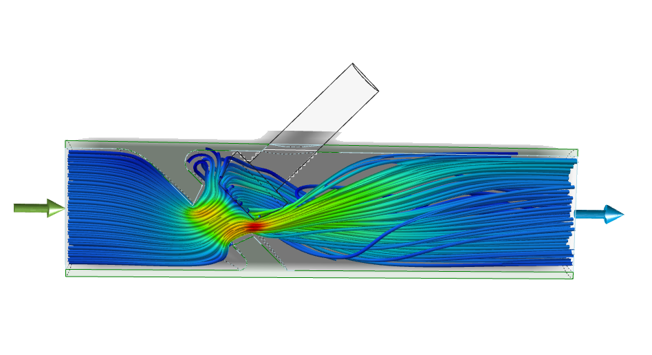
- For Result Types, select Velocity from the dropdown.
-
For Style, select Static Streamlines
 .
.
Post-process Results
-
To animate the run, select Animated Streamlines
 .
.
-
Deselect Static Streamlines and select
Vectors
 .
.
- In the microdialog, deselect Scale dimension.
-
Lower the diameter size from 5 to 3.
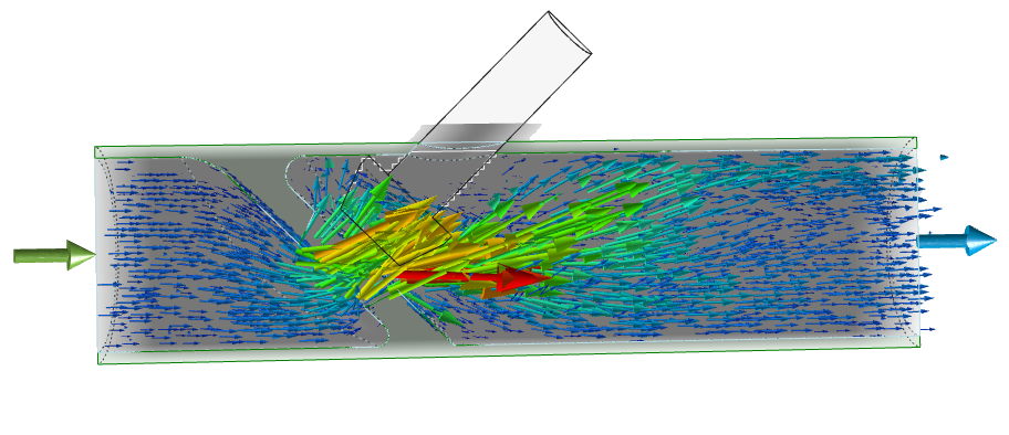
- Right-click and mouse through the check mark to exit, or double-right-click..
Move the Embedded Solid Domain
After translating the embedded solid, we can directly proceed to re-running the simulation without making any changes to the fluid domain or inlet/outlet conditions. This is the primary benefit of defining parts as embedded solids.
- Select the Move tool from the Home category.
-
Select the Plug.
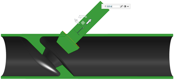
- Select the Z arrow, then enter 0.01 In the microdialog. This will translate the plug and create a wider valve opening.
- Right-click and mouse through the check mark to exit, or double-right-click.
-
On the Fluids ribbon, select the Create Fluid
Domain tool.
The static solid is automatically highlighted in red and the material microdialog opens. - Right-click and mouse through the check mark to exit, or double-right-click.
Re-Run the Analysis
Run analysis 2 for the Embedded Solids tutorial. After translating the embedded solid, you can directly proceed to re-running the simulation without making any changes to the fluid domain or inlet/outlet conditions.
- Click Fluids Quick Run.
-
View the new results:
-
In the Convergence Plot window, click next to Engineering
Quantities.
Notice that the wider valve opening provides less resistance to the fluid flow. Consequently, the predicted inlet pressure for the modified geometry configuration has reduced to 15937 N/m2.

-
In the Convergence Plot window, click
-
Compare the Velocity Magnitude Contours from simulation
1 and simulation 2.
-
The following velocity magnitude contours are from simulation 1:
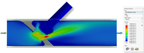
Notice the peak velocity magnitude for original configuration is 7.86 m/s.
-
The following velocity magnitude contours are from simulation 2:
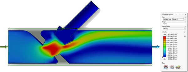
Notice the peak velocity magnitude for modified configuration is 6.21 m/s.
Due to a narrower opening in the original configuration in simulation 1, the fluid accelerates to a higher velocity compared to the wider opening scenario from simulation 2.
-
The following velocity magnitude contours are from simulation 1: