Elastic-plastic Orthotropic Composite Shells
- Composite shells with isotropic layers
- Composite shells with at least one orthotropic layer
- Material law COMPSH (25) with orthotropic elasticity, two plasticity models and brittle tensile failure,
- Material law CHANG (15) with orthotropic elasticity, fully coupled plasticity and failure models.
These laws are described here. The description of elastic-plastic orthotropic composite laws for solids is presented in the next section.
Tensile Behavior
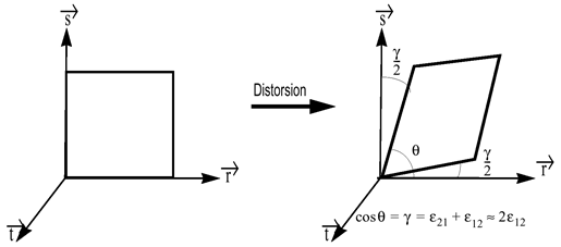
Figure 1. Shear Strain
- Tensile failure strain in direction 1
- Maximum strain in direction 1
- Tensile failure strain in direction 2
- Maximum strain in direction 2
- dmax
- Maximum damage (residual stiffness after failure)
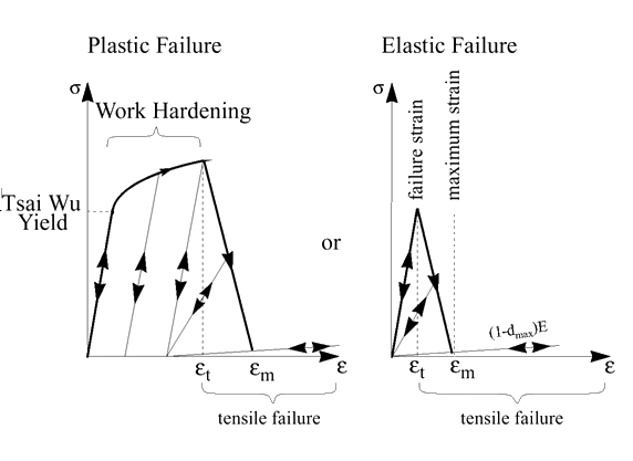
Figure 2. Tensile Behavior of Composite Shells
Delamination
Where, is the delamination damage factor. The damage evolution law is linear with respect to the shear strain.
for ⇒
for =1 ⇒
Plastic Behavior
- Tension in direction 1 of orthotropy
- Tension in direction 2 of orthotropy
- Compression in direction 1 of orthotropy
- Compression in direction 2 of orthotropy
- Compression in direction 12 of orthotropy
- Tension in direction 12 of orthotropy
- : elastic state
- : plastic admissible state
- : plastically inadmissible stresses
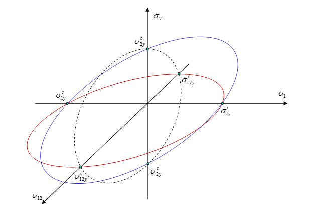
Figure 3. Cross-sections of Tsai-Wu Yield Surface For
- Hardening parameter
- Hardening exponent
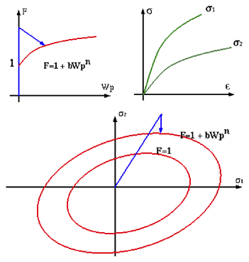
Figure 4. Isotropic Plasticity Hardening
Failure Behavior
- plastic work limit ,
- maximum value of yield function
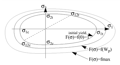
Figure 5. Evolution of Tsai-Wu Yield Surface
- If for one layer,
- If for all layers,
- If or tensile failure in direction 1 for each layer,
- If or tensile failure in direction 2 for each layer,
- If or tensile failure in directions 1 and 2 for each layer,
- If or tensile failure in direction 1 for all layers,
- If or tensile failure in direction 2 for all layers,
- If or tensile failure in directions 1 and 2 for each layer.
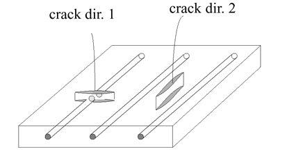
Figure 6. Crack Orientation
In practice, the use of brittle failure model allows to estimate correctly the physical behavior of a large rang of composites. But on the other hand, some numerical oscillations may be generated due to the high sensibility of the model. In this case, the introduction of an artificial material viscosity is recommended to stabilize results. In addition, in brittle failure model, only tension stresses are considered in cracking procedure.
The ductile failure model allows plasticity to absorb energy during a large deformation phase. Therefore, the model is numerically more stable. This is represented by CRASURV model in Radioss. The model makes also possible to take into account the failure in tension, compression and shear directions.
Strain Rate Effect
- Plastic work
- Reference plastic work
- Plastic hardening parameter
- Plastic hardening exponent
- Strain rate coefficient (equal to zero for static loading)
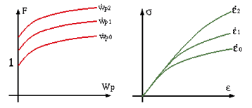
Figure 7. Strain Rate Effect in Work Hardening
CRASURV Model
With
With
(=12)
(=12)
And
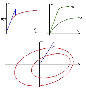
Figure 8. CRASURV Plasticity Hardening
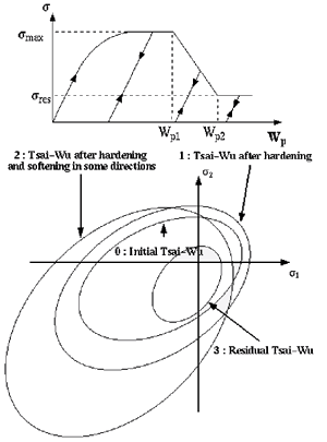
Figure 9. Flow Surface in CRASURV Model
Chang Chang Model
Chang-Chang law 2, 3 incorporated in Radioss is a combination of the standard Tsai-Wu elastic-plastic law and a modified Chang-Chang failure criteria. 4 The affects of damage are taken into account by decreasing stress components using a relaxation technique to avoid numerical instabilities.
- Longitudinal tensile strength
- Transverse tensile strength
- Shear strength
- Longitudinal compressive strength
- Transverse compressive strength
- Shear scaling factor
- Fiber direction
- Tensile fiber mode:
(20) - Compressive fiber mode:
(21)
- Tensile matrix mode:
(22) - Compressive matrix mode:
(23)
With: and
- Time
- Start time of relaxation when the damage criteria are assumed
- Time of dynamic relaxation
is the stress components at the beginning of damage (for matrix cracking ).