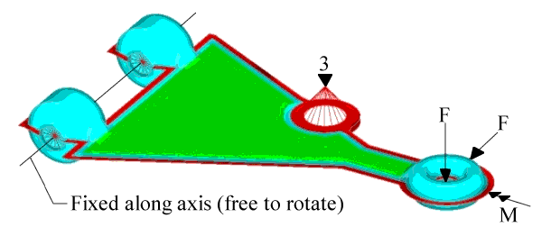
The shape of the bead reinforcements on the plates is optimized to withstand the
applied loads. The part is modeled as two layers of shell elements (green and blue)
connected with fringe elements (red). The model is pinned, but is free to rotate
about an axis at the frame attachments. A vertical constraint is placed at the shock
absorber attachment point. This point is connected to the fringe elements with rigid
bars. Vertical, lateral, and twisting loads are applied to the spindle
attachment.Figure 1. Loads and Constraints for the Stamped Control Arm Model
The elements shown in green are included in the design space. The nodes in the top
layer can move upward and the nodes on the bottom layer can move downward. Symmetry
is used to force the bead pattern on the top to match the one on the bottom. The
DTPG card is generated as:
(1)
(2)
(3)
(4)
(5)
(6)
(7)
(8)
(9)
(10)
DTPG
2
DVGRID
1
+
15.0
60.0
YES
PATRN
10
4184
1211
The plane of symmetry is normal to the vertical axis and is positioned running
through the center plane of the model.
The optimization objective function is simply defined as minimizing the sum of the
weighted compliance of all three load cases.
Results
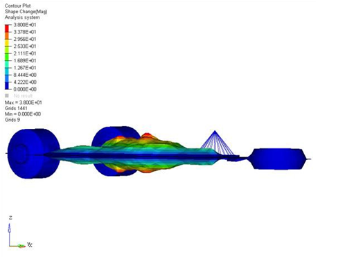
The solution for the model is shown in the figures below. Figure 2 shows the symmetry of the solution about
the vertical axis.Figure 2. OptiStruct Solution for the Stamped Control
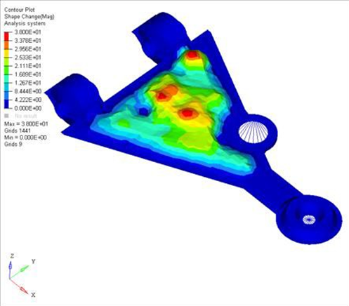
Arm Model, Side View Figure 3. OptiStruct Solution for the Stamped Control
Arm, Top View
The solution shows the importance of adding vertical bending stiffness in the area
around the shock absorber attachment point. OptiStruct
creates a large bead running from the upper frame attachment point, past the shock
attachment, and up to the spindle attachment (Figure 3).
This bead supports most of the bending load. In addition, there is vertical bending
which runs in the perpendicular direction. OptiStruct
creates a bead running from the shock attachment point to the lower frame attachment
(Figure 3). This second bead is not as pronounced
because there is less bending in that direction compared to the primary
direction.