OS-E: 3035 Surface Optimization of a Control Arm
Topography optimization has applications beyond creating beads in shell surfaces. Since the basic topography approach can be applied to any model containing large fields of shape variables, it lends itself to solid model applications, as well.
In the following example, global shape optimization of a solid part is performed by generating shape variables using the DTPG card.
Model Files
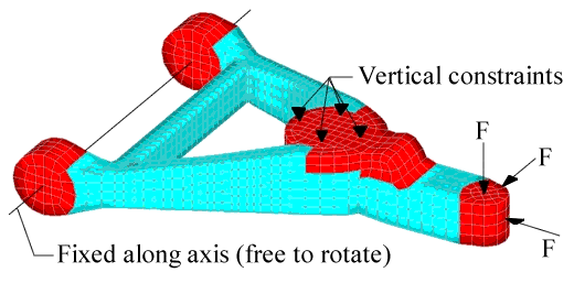
Model Description
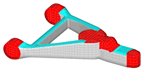
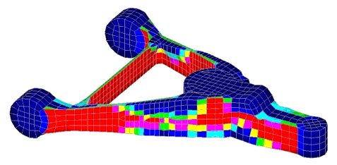
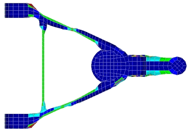
Results
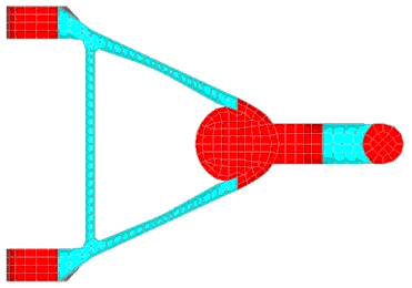
The side surfaces of the structural members are optimized in this example.
Shells are attached to the sides of the members. Define the normal vectors of those elements to point inward. Set the value of the draw height on the DTPG card so that the solid elements do not get turned inside out during shape optimization. If this occurs, OptiStruct gives an error and terminates the optimization. The lower bound on the DTPG card was set to -1.0 and the upper bound was set to 1.0, which allows the control arm to become larger or smaller.
The objective was set as minimizing the weighted sum of the compliance of the load cases while holding the mass of the part constant.