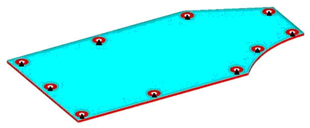
The plate is supported at ten bolt locations around its perimeter. The edge of the
plate is turned downward to add stiffness.Figure 1. Cover Plate Model with Constraints Shown
The red areas are excluded from the design domain. The blue area is open for OptiStruct to add a bead reinforcement pattern. The bead is
drawn upward with respect to the plate orientation. The DTPG card
used is as follows. Four different runs were made using different values for the
draw height. The first run was made with a draw height of 20mm, the second with
40mm, the third with 60mm, and the fourth with 80mm.
(1)
(2)
(3)
(4)
(5)
(6)
(7)
(8)
(9)
(10)
DTPG
1
PSHELL
5
20.0
60.0
YES
20.0
NORM
NONE
The optimization is set up to maximize the frequencies of the first six modes
(minimizing the sum of the weighted inverse eigenvalues) and to ensure that the
first three modes were above certain design constraints. This is accomplished by
placing the following cards in the subcase definition:
DESOBJ(MIN)
1
DESSUB
101
The following cards are placed in the Bulk Data section:
DRESP1
11
freq1
FREQ
1
DRESP1
12
freq2
FREQ
2
DRESP1
13
freq3
FREQ
3
DRESP1
1
wfreq
WFREQ
DCONSTR
101
11
400.0
DCONSTR
101
12
500.0
DCONSTR
101
13
600.0
DRESP2
1
wfreq
900
Results
Setting constraints on the first three modes results in separations
between the frequency values of the modes and prevents OptiStruct from falling into local
minimums when optimizing the modes. This approach ensures that a
minimum performance criterion is satisfied.
Note: For the 40mm,
60mm, and 80mm draw height runs, the constrained frequencies
are higher than those shown above.
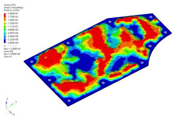
The solutions generated for the plate runs are:Figure 2. Solution for Plate with Draw Height Equal to
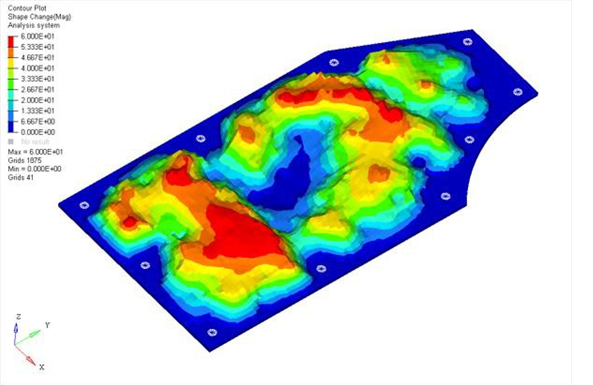
20mm Figure 3. Solution for Plate with Draw Height Equal to
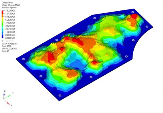
40mm Figure 4. Solution for Plate with Draw Height Equal to
60mm Figure 5. Solution for Plate with Draw Height Equal to
80mm
The reinforcement patterns have a similar shape, but runs with a higher
maximum draw height use more levels of draws throughout the plate.
All of the solutions made good engineering sense, connecting the
weak areas of the plate with beads running primarily across the
short span of the plate. These beads were fluidly connected across
the long span of the plate allowing the beads to reinforce each
other.