OS-E: 3010 Multi-plane Symmetric Reinforcement Optimization for a Pressure Vessel
A rectangular thin-walled box is to be used to store fluid. The outward bulging of
the sides of the container (due to the pressure of the contents) is to be minimized.
Additionally, the maximum outward displacement of the side panels must be below a given
value.
Model Files
Before you begin, copy the file(s) used in this example to
your working directory.
The model is shown in Figure 1. All optimization set up is done using the optimization panel and its subpanels
in HyperMesh.
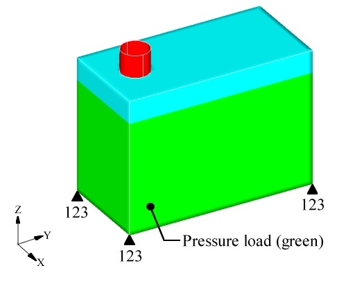
The model is constrained for displacement in all directions at the four lower corners
but is free to rotate about those constraints. The loading is a distributed pressure
through the area shown in green. The pressure is higher at the bottom of the
vessel.Figure 1. Loads and Constraints on Rectangular Pressure Vessel
The entire box is to be used as the design domain with the exception of the filling
hole on the top shown in red. All of the elements in the design domain are placed in
the same component and reference the same material property. The normal vectors for
all of the elements in the design domain are pointing outward. The topology
variables are set up with the following DTPG card:
(1)
(2)
(3)
(4)
(5)
(6)
(7)
(8)
(9)
(10)
DTPG
1
PSHELL
1
+
7.0
60.0
YES
5.0
NORM
NONE
+
PATRN
30
50.0
100.0
75.0
0.0
1.0
0.0
+
PATRN2
0
0.0
0.0
1.0
+
BOUNDS
0.0
1.0
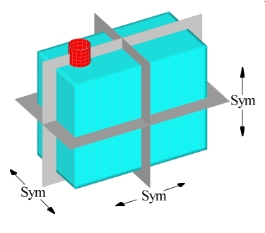
Three orthogonal planes of symmetry are defined (Figure 2). The anchor node is placed at the center of the box. The first and second
vectors are defined parallel to the X and Y axes. The first vector is defined
pointing away from the filler cap. This ensures that the automatically generated
variables will cover the entire surface of the box. If the first vector was pointing
in the other direction, the symmetry method would reflect the lack of variables in
the area of the filler cap across all three planes of symmetry.Figure 2. Orthogonal Symmetry Planes for the Pressure Box
The objective is to minimize compliance for the pressure load case, which is the same
as minimizing the strain energy of the entire model. The displacement of the center
point of each of the five loaded surfaces was constrained to be less than a given
value.
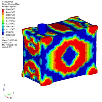
OptiStruct generated the following solution for the
pressure box shown in Figure 3.Figure 3. OptiStruct Solution for the Pressure
Box
The OptiStruct solution met all of the optimization
constraints and yielded a good design. The areas shown in red (Figure 3) are the bead reinforcements that OptiStruct created
to increase the stiffness of the model. The solution is unconventional, but makes a
good deal of engineering sense. For the large side panels and the top and bottom
panels of the box, OptiStruct has generated large,
rounded, centrally located reinforcement beads. These types of beads are very
effective in stiffening the panels against a distributed or central load. This is
due to the fact that bending in the central areas of the panels is occurring in two
directions, both vertically and horizontally. The rounded beads create stiffness in
both directions and are weak in neither. At the eight corners of the model, OptiStruct created beads that anchor the sides of the box
together allowing each side of the box to gain support from the neighboring
sides.
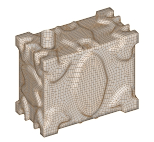
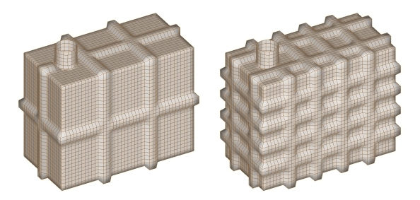
A finite element model was created from this reinforcement pattern (Figure 4).Figure 4. Finite Element Model of the OptiStruct
Solution for the Pressure Box
This pattern was compared to two other bead reinforcement designs shown in Figure 5.Figure 5. Conventional Reinforcement Patterns for the Pressure Box
The OptiStruct model is superior in stiffness to both of
the two conventional models. The maximum deflection of the OptiStruct model was 30% less than the lightly reinforced
conventional model (the one on the left), and 46% less than the heavily reinforced
model (the one on the right). The lightly reinforced model was stiffer than the
heavily reinforced model, which goes against the assumption that more reinforcements
result in increased stiffness. With bead type reinforcements that assumption is not
always true, which demonstrates the effectiveness of topography optimization.
OptiStruct delivers an optimized first design,
eliminating the need to do a series of re-designs where the second, third, fourth,
etc., model does not always result in an improvement.
Manufacturing constraints can be accounted for in the pressure box model using other
pattern grouping options. The set up is done easily through the HyperMesh interface. In order to manufacture the pressure box
using a two piece die mold, bead reinforcements that run laterally would need to be
eliminated or else they would cause a die lock condition. Topography optimization
can be used to generate reinforcement beads on the sides of the box that run
vertically only. This is done by using separate topography variables for the side
walls, front and back panels, and the top and bottom panels. Topography variables
with planar symmetry with one plane symmetry grouping type are defined for the side
panels and the front/back panels, respectively. As in the earlier case, a three
plane symmetry topography variable is assigned for the top/bottom panels. The two
cards are shown below and differ only in the direction of the first vector.
(1)
(2)
(3)
(4)
(5)
(6)
(7)
(8)
(9)
(10)
DTPG
1
PSHELL
1
+
7.5
60.0
YES
5.0
NORM
NONE
+
PATRN
13
50.0
100.0
75.0
0.0
1.0
0.0
+
BOUNDS
0.0
1.0
(1)
(2)
(3)
(4)
(5)
(6)
(7)
(8)
(9)
(10)
DTPG
1
PSHELL
1
+
7.5
60.0
YES
5.0
NORM
NONE
+
PATRN
13
50.0
100.0
75.0
1.0
0.0
0.0
+
BOUNDS
0.0
1.0
Results
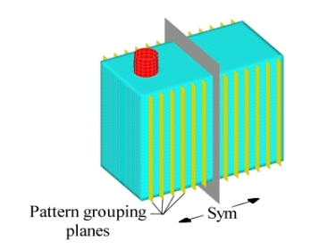
The planes for the planar pattern grouping run vertically and perpendicular to the
Y-axis, which causes OptiStruct to generate vertical
beads. Because the planes run through both sides of the box, there will be symmetry
between opposing sides. Also, symmetry on either side of the anchor node in the
direction of the first vector (Y-axis) is forced with the one plane symmetry option
(pattern grouping option 13). (Figure 6)Figure 6. Planar Pattern Grouping Planes for Sides of Pressure Box
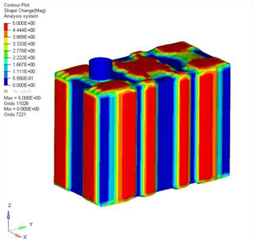
With planar symmetry enforced for the sides of the pressure box and three-plane
symmetry enforced on the top and bottom of the box, OptiStruct generated the solution shown in Figure 7. Even without the presence of lateral beads on the sides of the box, the OptiStruct solution shown below had a maximum deflection 6%
less than the lightly reinforced conventional model.Figure 7. Pressure Box Solution for Combined Three-Plane and Planar Symmetry
Options