OS-E: 3040 Forge a Design Reference Out of a Solid Block
Pattern grouping lends itself very well to applications where manufacturing
conditions must be met. In this example, topography optimization is used to form a design
concept out of a solid block. Manufacturing the design concept using a casting method is
preferable.
Model Files
Before you begin, copy the file(s) used in this example to
your working directory.
All optimization set up is done using the Optimization panel and its subpanels in
HyperMesh.
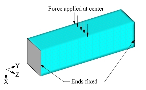
A solid rectangular block is fixed at both ends and loaded in the center (Figure 1).Figure 1. Loads and Constraints for the Solid Block Model
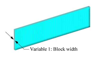
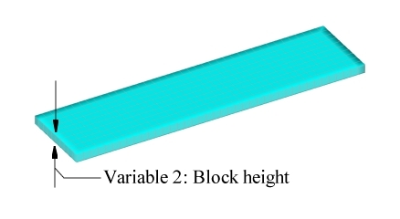
Two shape variables are generated using HyperMesh to
control the height and width of the block. (Figure 2 and Figure 3)Figure 2. User-Defined Variable #1 Figure 3. User-Defined Variable #2
It is preferable to manufacture the resulting part using a casting process. This can
be accomplished by using a linear pattern grouping in the casting draw direction and
a planar pattern grouping perpendicular to the draw. This will ensure that there are
no cavities that would create a die lock situation.
Thinking ahead, it is predictable that the cross-section of the solution will be
roughly an I-shaped section with the web running vertically. This prediction
establishes the draw direction as being horizontal, which corresponds to variable #1
(block width), thus variable #1 will be split using linear pattern grouping and
variable #2 will be split using planar pattern grouping. The DTPG
cards and associated DESVAR cards are shown below:
(1)
(2)
(3)
(4)
(5)
(6)
(7)
(8)
(9)
(10)
DTPG
3
DVGRID
1
+
2.0
60.0
NO
+
PATRN
21
50.0
250.0
50.0
0.0
0.0
1.0
+
PATRN2
0.0
1.0
0.0
(1)
(2)
(3)
(4)
(5)
(6)
(7)
(8)
(9)
(10)
DESVAR
1
DV001
0.0
0.0
1.0
(1)
(2)
(3)
(4)
(5)
(6)
(7)
(8)
(9)
(10)
DTPG
4
DVGRID
2
+
20.0
60.0
NO
+
PATRN
13
50.0
250.0
50.0
0.0
1.0
0.0
(1)
(2)
(3)
(4)
(5)
(6)
(7)
(8)
(9)
(10)
DESVAR
2
DV002
0.0
0.0
1.0
The linear variable dispersion pattern for variable #1 allows OptiStruct to control the thickness of the block at numerous
points across its side giving the solution a great deal of flexibility. The planar
variable dispersion pattern for variable #2 allows OptiStruct to control the height of the cross-sections along
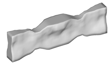
the length of the block. The objective was to minimize the mean compliance of the
block under the given load. The mass was constrained to be below one fourth of the
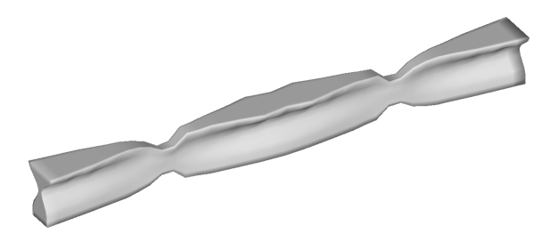
initial mass of the block. OptiStruct generated the
solution, shown in Figure 4.Figure 4. OptiStruct Solution for the Solid
Block
Results
The cross-section of the block is roughly I shaped, concentrating the material at the
top and bottom of the end and center areas where the bending moment is the greatest.
The design is flat and tall in areas where shear is dominant. The solution is
manufacturable by use of a casting process since there are no cavities or die lock
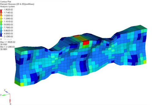
conditions. The efficiency of the solution can be seen by looking at the stress
contours. The nearly uniform stress distribution, shown in Figure 5, indicates that almost every part of the structure is being used to its fullest
potential.Figure 5. Stress Contours for the OptiStruct
Solution
The maximum dimensions of the block were reduced by 2.5 times and a second topography
optimization was performed. The solution OptiStruct
produced is shown in Figure 6.Figure 6. OptiStruct Solution for Solid Block with 2.5
Times Smaller Cross-Section
The basic shape of the block is the same in the reduced dimension model, but has more
pronounced features. The I shaped cross-sections in the center and at the ends have
wider flanges, and the shear carrying areas in between are thinner. This makes sense
considering the smaller dimensions increase the need for bending stiffness more than
the need for shear stiffness.