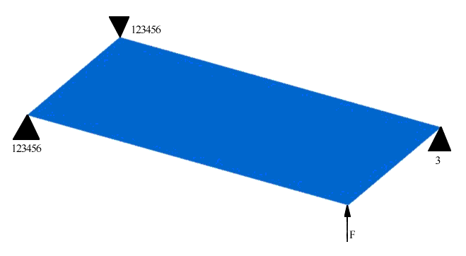
A specific part of the structure is to be loaded in torsion (Figure 1).
The part is to be formed using a stamping process.
Only the shape of the plate can be changed, the thickness cannot be
changed.
Figure 1. Loads and Constraints
Topography optimization divides the design region into smaller areas, each with its
own shape variable. OptiStruct performs this process
using the parameters defined by the user. The design space consists of the entire
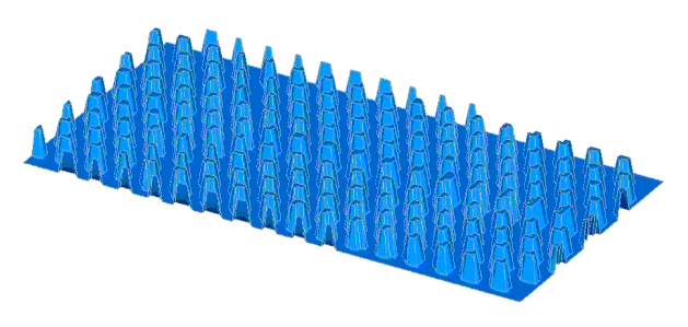
plate minus the areas near the loads and constraints. The smaller areas can each
move upward. The inner portions of these smaller areas are shown fully deflected in
Figure 2.Figure 2. Inner Portions of the Shape Variables for the Plate
The potential reinforcement pattern can be any combination of these variables
deflected at any height between zero and the user-defined maximum height. OptiStruct creates a reinforcement pattern of any shape by
manipulating the 174 discrete shape variables. The pattern could resemble an X, an
oval, a series of straight beads, or any number of the millions of potential
designs. By setting various parameters, you can ensure that any design OptiStruct creates is manufacturable.
Once OptiStruct generates the shape variables, it begins
the optimization of the plate. The objective in this example is simple, the
stiffness of the plate under the given torsion load is to be maximized. OptiStruct performs a series of analysis runs to evaluate the
stiffness of the plate, determines what variable value changes will improve the
stiffness of the plate, and applies those changes to the model. After much
iteration, OptiStruct reaches the maximum design at a
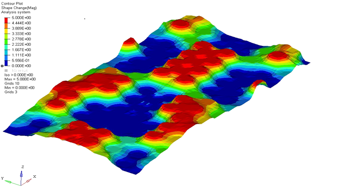
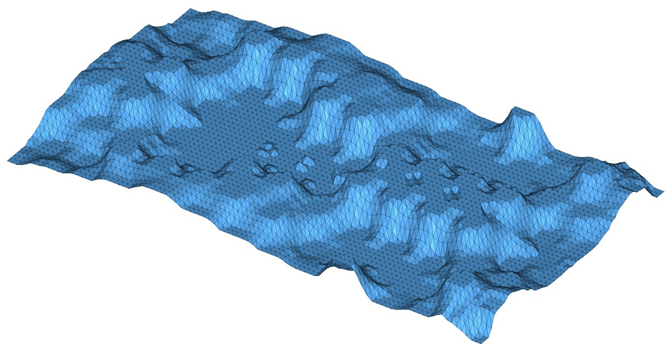
point where the stiffness can no longer be improved. The solution is shown in Figure 3 where the colors display the heights of the bead reinforcement patterns. A finite
element model based on that solution is shown in Figure 4. The symmetry of the solution is due to the use of an OptiStruct design symmetry plane feature.Figure 3. OptiStruct Bead Reinforcement Pattern for a
Plate in Torsion Figure 4. Finite Element Model Built from OptiStruct
Results
The face of the plate is covered with X-shaped cross-beads that work well in torsion.
None of the beads run completely across the plate in a straight line which would
reduce their effectiveness. Finite element analysis of the plate revealed a well
distributed stress pattern and low deflection at the load point.
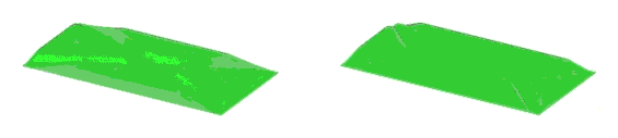
The traditional method is to design a reinforcement pattern in the form of raised
"beads" across the surface of the plate, test the stiffness of the plate, and
increase the stiffness of the plate until it meets the design requirements. The
efficiency of the plate in terms of cost and weight is strongly dependent upon how
good the reinforcement pattern is, so it is critical to generate a good one. Two
examples of conventional bead reinforcement patterns for the plate in twisting model
are shown in Figure 5. These patterns are ones which would commonly be found in commercial
products.Figure 5. Common Bead Reinforcement Patterns for a Plate in Torsion
Results
The plate generated by OptiStruct using topography
optimization is far stiffer than both of the conventional plates shown in Figure 5. Peak deflection for the topography plate is 0.83mm. For the conventional plates,
the peak deflections are 1.27mm for the one on the left and 6.47mm for the one on
the right. The plate developed with OptiStruct is 35%
stiffer than a good conventional design and far better than a poor one. The poor
design, while following the conventional wisdom of using an X-shaped reinforcement
pattern, uses beads that run completely across the plate in a straight line which
are susceptible to kinking when loaded. Such design mistakes are caught and
corrected by OptiStruct during the optimization process
allowing it to yield a superior design.