
Phase 1: Reference Level Design
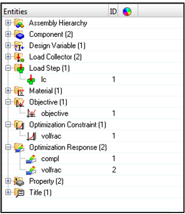
- Objective
- Minimize compliance
- Constraints
- Volume Fraction (0.3)
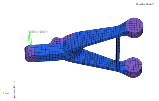
- Design Spaces
- "design" PSOLID (5) and Stress constraint (200)
- Responses
- Compliance and Volume Fraction
Lattice optimization differs from topology as a concept-level optimization in that elements with intermediate densities will be mathematically interpreted as solid, lattice, or void, depending on your settings in the setup phase. You will add continuation cards and parameters in a text editor to change this from standard topology to lattice optimization.
Launch HyperMesh and Set the OptiStruct User Profile
-
Launch HyperMesh.
The User Profile dialog opens.
-
Select OptiStruct and click
OK.
This loads the user profile. It includes the appropriate template, macro menu, and import reader, paring down the functionality of HyperMesh to what is relevant for generating models for OptiStruct.
Import the Model
-
Click .
An Import tab is added to your tab menu.
- For the File type, select OptiStruct.
-
Select the Files icon
 .
A Select OptiStruct file browser opens.
.
A Select OptiStruct file browser opens. - Select the controlarm.fem file you saved to your working directory.
- Click Open.
- Click Import, then click Close to close the Import tab.
Set Up the Optimization
Add LATTICE Continuation Card to the DTPL Card
- From the topology panel on the optimization page, select the update subpanel.
-
For desvar =, enter dtpl and activate the checkbox for
lattice optimization.
This will bring up additional parameters for the lattice optimization.
- For lattice type=, select 1.
-
Activate the checkboxes and enter the associated parameters.
Figure 3. 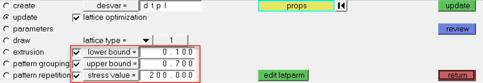
-
Click update to update the topology design
variable.
Any elements with a topology density below the lower bound value will be considered void (empty) at the end of Phase 1 and any elements with a topology density above the upper bound will be considered fully solid. Elements whose element density is between the lower and upper bound are considered porous and will be replaced by lattice elements at the end of Phase 1.
Add DOPTPRM Optimization Parameters
Controls the optimization.
- From the topology panel on the update subpanel, click edit latparm to enter:
-
Activate the checkboxes and set the associate fields.
Figure 4. 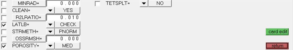
- Click return to exit the lattice parameter editor and click update to ensure that the design variable is properly updated.
- Click return to exit the topology panel.
Run the Optimization using OptiStruct
- Open the Compute Console (ACC).
- Open the controlarm.fem file.
-
Click Run to run the optimization.
- When the optimization has completed, open the controlarm.fem file in a text editor.
- Check how the optimization progressed. Make sure that the optimization is fully converged and that the constraint is satisfied.
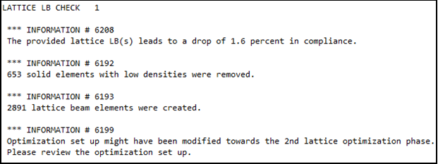
Since DOPTPRM, LATLB, CHECK was applied, OptiStruct checked the drop-in compliance, due to the removal
of elements with density below LB. The drop is relatively small and this LB can be
considered a good choice.